GAS-FIRED VENTED WALL FURNACE Installation and Operating Instructions NATURAL GAS - W255GPPR, W255GPPD, W355GPPR, W355GPPD, W505GPPR & W505GPPD ! WARNING: If the information in these instructions is not followed exactly, a fire or explosion may result causing property damage, personal injury or loss of life. — Do not store or use gasoline or other flammable vapors and liquids in the vicinity of this or any other appliance. — WHAT TO DO IF YOU SMELL GAS • Do not try to light any appliance.
CONTENTS READ CAREFULLY BEFORE INSTALLING UNIT Before Installation Standards ............................................ 2 Specifications ...................................... 3 Introduction ......................................... 4 Safety .................................................. 4 Clearances .......................................... 5 Controls & Orifices ............................... 5 Combustion & Venting .....................
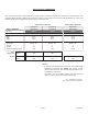
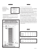
SPECIFICATIONS & DIMENSIONS Your vented wall furnace comes packed in a single carton. Included in the box: the thermostat, thermostat wire, and insulated staples. Before installing the wall furnace check the rating plate to verify that the Model Number is correct and that the wall furnace is equipped for the type gas you intend to use. SINGLE WALL FURNACES DOUBLE WALL FURNACES W255GPPR W255GPPD W355GPPR W355GPPD W505GPPR W505GPPD Natural Natural Natural Millivolt Wall Stat. Millivolt Wall Stat.
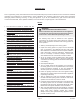
INTRODUCTION This is a gas-fired, gravity vented wall furnace that will operate safely and provide an efficient source of heat when installed, operated and maintained as recommended in these installation and operating instructions. Read these instructions thoroughly before installing, servicing, or using the appliance. If you do not understand any part of these instructions, consult local authorities, other qualified installers, service technician, the gas supplier or the manufacturer. SAFETY 1.
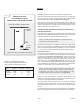
CLEARANCES As viewed from the front of heater, these are the minimum clearances from cabinet to combustible construction: CONTROLS All controls are preassembled at the factory. Side Wall - 1” without Pilot Pro Cover The normal manifold pressure should be 3.5” w.c. on Natural Gas. The maximum inlet pressure in the gas supply pipe should never exceed 7.0” w.c. on Natural Gas.
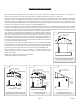
COMBUSTION AND VENTILATION AIR When installed, this gas appliance must be provided with fresh air for combustion, ventilation, and dilution of hot flue gases. The minimum required volume of the area where the appliance is installed should be 50 cubic feet per 1,000 btu/hr. If installed in an area of the home that is considered an unconfined space, the natural infiltration of air around windows and doors will be adequate.
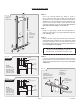
VENTING This appliance must be properly connected to a venting system. FIG. 2 USING ADJACENT STUD SPACE FOR ALL COMBUSTION AIR FROM OUTSIDE Holes Connecting to Ventilated Attic Ceiling Plate Consult local ordinances governing venting. Install only UL listed type BW 4” oval gas vent. When the vent enters the attic, a listed type B-1 round flue pipe may be used. See Figure 7-A (on page 9).
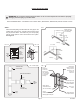
ROUGH-IN INSTRUCTIONS ! WARNING: Do not bypass the blocked flue switch. To do so could expose the consumer to property damage, personal injury or possible death. NOTE: MAXIMUM WALL THICKNESS FOR A DUAL WALL (W505GPPR, W505GPPD) INSTALLATION IS 5-3/8”. STEP 1. FIG. 3 Attach the base plate (purchased with the vent pipe) to the header plate using two No. 8 sheet-metal screws through the pre-punched holes. The heater may not vent properly without a base plate to anchor and seal the vent system.
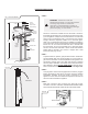
ROUGH-IN INSTRUCTIONS STEP 2. FIG. 7-A Cut out an opening between the studs of 14-3/8” x 66-1/2” above the floor plate. Embed the rear flange of the channel on top of header into either the drywall or the plastered wall. This provides part of the required fire stop. Square up and nail the header in place with the top front of header located 65-3/4” above floor plate. See arrow on right side of header & Fig. 7-A, 7-B and 7-C. Rough-In Dimensions STEP 3. *65 3/4” ” 14 / .
ROUGH-IN INSTRUCTIONS STEP 6. FIG. 7-E: Vent Installation 2’ Min. Listed Vent Top Storm Collar Roof Flashing Ceiling Plate Spacers Oval to Round Adapter Listed “BW” Vent Pipe 12’ Min. Base Plate Ceiling Plate Spacer Lances Header Plate 2x4 Wall Studs ! WARNING: Failure to locate the thermostat properly or to wire the furnace correctly may result in continuous operation, control damage or failure to operate. This can cause property damage, personal injury, or loss of life.
INSTALLATION STEP 10. 30 - Remove the door from the heater housing. - Locate the Pilot Pro in the carton and remove the cover from baseplate with a screwdriver. - The Pilot Pro may be installed near the base of either side of the heater housing. When selecting a side for installation, be sure to allow room for future removal of the pilot pro cover. A C - Check the inside of the housing for safety labels. Try to avoid drilling through any pertinent safety information during this step.
INSTALLATION STEP 11. 34 34 With a phillips-head screwdriver, attach the controls assembly to the side of the heater using: 34 - x3 Screws #8-32 x 3/4” (34) - x3 Nuts #8 (36) DO NOT use a powered drill for this step, it could crack the mounting plate. USE A SCREWDRIVER AND HAND-TIGHTEN ONLY. 36 36 STEP 12. FIG. 8-C To fasten front panel to furnace, be sure exposed portion of header is free of debris.
INSTALLATION STEP 13. Direct the control module wires (29) through the small notch on the side of the mounting plate (30). Tuck the wires around the edge of the heater housing, against the wall, and inside the heater. 29 29 30 30 On the inside of the heater, you will see orange and black wires extending from the burner. Lead the orange pilot ignitor wire (40) and black flame sensor wire (42) out of the heater beside the wires you have just directed in.
ELECTRICAL CONNECTION WARNING: Please Use Caution While Installing the Electrical Connection STEP 1. Plug the orange wire from Ignitor (40) into the port labeled "I" on the control module (29). Ensure it is firmly seated. 29 I 40 STEP 2. Plug the black flame sensor wire (42) into the port labeled "S" on the control module (29). Ensure it is firmly seated. S 42 NOTE: Base of the connector terminal may be slightly exposed.
ELECTRICAL CONNECTION WARNING: Please Use Caution While Installing the Electrical Connection STEP 3. 29 48 30 Run a cable tie (48) through the small hole beside the notch on the mounting plate (30). Gather all the wires from the control module (29) with the cable tie (48). Guide any excess wire length back into the heater. STEP 4. TH - Connect Black TP wire to the TP terminal of valve. PILOT black wire IN - Connect Green TH wire to TH terminal of the valve.
ELECTRICAL CONNECTION WARNING: Please Use Caution While Installing the Electrical Connection STEP 5. WARNING: The two brown wires must be wired properly to prevent carbon monoxide poisoning or death. ue fe t it c h Bl Sa w yS B C 38 B n r ow W W ir e Ba r e Blue Sa f e t y S w i t c h W i r e ! Connect the brown male blade quick connect SWI wire from the control module wiring harness (38) to the blue female quick connect from safety switch. I BB.
ELECTRICAL CONNECTION WARNING: Please Use Caution While Installing the Electrical Connection CAUTION: Label all wires prior to disconnection when servicing controls. Wiring errors can cause improper and dangerous operation. Verify proper operation after servicing and secure wires away from sharp edges, flames or hot surfaces inside and outside the unit. STEP 6.
ELECTRICAL CONNECTION WARNING: Please Use Caution While Installing the Electrical Connection FOLLOW THIS STEP IF THE PILOT PRO IS ON THE RIGHT SIDE OF THE HOUSING. (Proceed to step 7-B if the Pilot Pro is on the left side of the housing). Make certain wiring connections are tight before proceeding and secure so they will not be able to contact high temperature locations. STEP 7-A. 48 A A. Route the wires around the back edge & inside the heater housing.
ELECTRICAL CONNECTION WARNING: Please Use Caution While Installing the Electrical Connection FOLLOW THIS STEP IF THE PILOT PRO IS ON THE LEFT SIDE OF THE HOUSING. (Go back to step 7-A if the Pilot Pro is on the right side of the housing). Make certain wiring connections are tight before proceeding and secured so they will not be able to contact high temperature locations. STEP 7-B. 48 A A. Route the wires around the back edge and inside the heater housing.
STARTING PILOT PRO SYSTEM PER ANSI Z21.71 STEP 1. Turn on all gas and electricity to the appliance. Conduct a gas leakage test of the appliance piping & control system downstream of the shutoff valve in the supply line to the appliance. STEP 2. ! Adjust thermostat to lowest setting. Place two D Batteries (46) in the Battery pack (28). 46 2c. IF PILOT DOES NOT LIGHT: Lower thermostat to OFF, then turn it back up. 2d. Ignitor will start to spark. 2e.
STARTING PILOT PRO SYSTEM PER ANSI Z21.71 STEP 3. ! Ensure Ignitor sparks only against the hood of the pilot. Ignitor should not spark against the flame sensor, brackets, heating chamber, burner, etc. Adjust ignitor probe location if required. - DO NOT twist ignitor wire or break from ceramic base. - DO NOT use a broken ignitor. STEP 4. Determine that the pilot is igniting and burning properly and that main burner ignition is satisfactory by turning the thermostat off and back on.
STARTING PILOT PRO SYSTEM PER ANSI Z21.71 STEP 6. Slide the Pilot Pro cover (31) over the controls. Secure in place with: - 33 x2 Screw with knob (33) 31 NOTE: Hand-tighten only. Do not over tighten. 33 STEP 7. ! WARNING: CARBON MONOXIDE POISONING HAZARD Failure to follow the steps outlined below for each appliance connected to the venting system being placed into operation could result in carbon monoxide poisoning or death.
LIGHTING INSTRUCTIONS - ( IID PILOT ) MODELS: W255GPPR W255GPPD / W355GPPR W355GPPD Page 23 / W505GPPR W505GPPD 1018454-E
MAINTENANCE INSTRUCTIONS STEP 1. Installation and repair must be done by a qualified service person. The appliance should be inspected before use and at least annually by a professional service person. More frequent cleaning may be required due to excessive lint from carpeting, bedding material, etc. It is imperative that control compartments, burners, pilot burners, circulating air passageways and venting systems of the appliance be kept clean. STEP 2.
BURNER FLAME ADJUSTMENT ( Stainless Steel Burner ) IID PILOT LADDER SCHEMATIC W255GPPR, W255GPPD, W355GPPR, W355GPPD, W505GPPR & W505GPPD FIG. 11 THERMOSTAT 1 AIR SHUTTER 1. FLAME TOO SOFT Yellow Flame. Open air shutters until yellow tipping disappears. MANUAL RESET 2 IGNITION MODULE 2. FLAME TOO HARD GAS VALVE Deep Blue Coloration. Closing air shutters to a point where yellow tipping begins, re-open slightly to eliminate yellow tipping. Air shutter adjustment is now correct. BATTERY 3 ! 3.
40542-A REAR REGISTER KIT (Optional Accessory) Installation Instructions for Gravity Vented Wall Furnaces STEP 1. Cut hole within stud space behind heater in the back wall 8-1/4” high by 12-5/8” wide. The lower edge of the hole to be 45-3/4” above the floor plate or 47” from the floor (with standard 2”x4” floor base) as shown in Figure 12-A (below). STEP 2. Install plaster ground frame for rear register in hole and nail frame to stud as shown in Figure 12-B (below). STEP 3.
40542-A REAR REGISTER KIT ( OPTIONAL ACCESSORY ) - Continued Installation Instructions for Gravity Vented Wall Furnaces FIG. 13-A FIG. 13-C INNER PANEL PLASTER GROUND FRAME DAMPER OPEN POSITION CLOSED POSITION CASING REAR REGISTER GRILLE FINISHED WALL 2” X 4” UPRIGHT FIG.
MODEL WFF81-C OPTIONAL FAN KIT - (Optional) Installation Instructions FIG. 13 NOTE: This fan kit is to be installed after installation of the wall furnace and with the wall furnace front panel in place. JUNCTION BOX STEP 1. This appliance, when installed, must be electrically grounded in accordance with local codes, or in the absence of local codes, with the latest edition of the National Electric Code, ANSI/NFPA No. 70. In Canada, see the current Canadian Electrical Code CSA C22.1. STEP 2.
TROUBLESHOOTING W255GPPR, W255GPPD, W355GPPR, W355GPPD, W505GPPR & W505GPPD Cozy Heating Systems, LLC | cozyheaters.
TROUBLESHOOTING CHART ( FOR QUALIFIED SERVICE TECHNICIAN ) MAIN BURNER Please follow the following corrective actions in order. SYMPTOM Flame Too Large POSSIBLE CAUSES CORRECTIVE ACTION 1. Defective operator section of gas valve. 1. Replace complete valve. 2. Burner orifice too large. 2. Check with local gas company for proper orifice size & replace. 3. If installed above 2,000 ft. 3. Refer to orifice chart, Page 5. Flame Pops Back 1. Too much primary air. 1. Adjust air shutter. (See Page 25).
TROUBLESHOOTING CHART ( FOR QUALIFIED SERVICE TECHNICIAN ) MAIN BURNER Please follow the following corrective actions in order. SYMPTOM Failure to Ignite POSSIBLE CAUSES CORRECTIVE ACTION 1. Main gas off. 1. Open all manual gas valves. 2. Defective gas valve. 2. Replace gas valve. 3. Defective pilot assembly. 3. Inspect pilot assembly for loose or broken components or wires. Replace. Refer to parts list. 4. Battery is low. 4. Turn thermostat off and replace batteries. 5.
TROUBLESHOOTING CHART ( FOR QUALIFIED SERVICE TECHNICIAN ) BLOCKED FLUE SWITCH Please follow the following corrective actions in order. POSSIBLE CAUSES CORRECTIVE ACTION A. Check vent pipe for blockage, such as bird nest, wasp nest, twigs, leaves, etc. Blockage in Vent Pipe B. Check inside the bottom of the vent pipe to make sure the top of the draft diverter did not rip the inner liner causing it to block part of the vent opening. C.
PARTS LIST W255GPPR, W255GPPD, W355GPPR, W355GPPD, W505GPPR & W505GPPD Cozy Heating Systems, LLC | cozyheaters.
PARTS LIST - ( GRAVITY WALL FURNACE ) SINGLE WALL FURNACE PARTS DUAL WALL FURNACE PARTS Natural Gas: W255GPPR, W255GPPD, W355GPPR & W355GPPD Natural Gas: W505GPPR & W505GPPD 10 1 10 5B 8 5A 1 8 26 25 7 5A 1 4 7 9 26 25 7 2 6 4 6 9 3 2 21 3 THERMOSTAT: 21 6 9 2 THERMOSTAT: 12 BURNER ASSEMBLY: When ordering any component in the Burner Assembly, specify either Honeywell or Robertshaw components.
PARTS LIST - ( GRAVITY WALL FURNACE ) ATTN: Contractors and Qualified Service Technicians: We only sell parts through our wholesalers. For prompt parts service, contact the wholesaler from which you purchased your Cozy heater. W255GPPR W255GPPD W355GPPR W355GPPD W505GPPR W505GPPD PART DESCRIPTION PART NO. PART NO. PART NO.
PARTS LIST - ( GRAVITY WALL FURNACE ) 36 36 Gravity Wall Furnace IID: 34 36 29 36 34 31 36 30 36 36 33 34 34 32 32 34 IID Pilot Assembly: 28 33 52 35 40 27 38 39 37 42 41 50 49 51 51 NOTE: Parts & schematic drawings on current models are shown at: cozyheaters.com | Specifications subject to change without notice.
PARTS LIST - ( GRAVITY WALL FURNACE ) ATTN: Contractors and Qualified Service Technicians: We only sell parts through our wholesalers. For prompt parts service, contact the wholesaler from which you purchased your Cozy heater. W255GPPR, W255GPPD, W355GPPR, W355GPPD, W505GPPR and W505GPPD Model Numbers. . . . . . . . . . . . . . . . . . . . . . . . . . . . . . . . . . . PART DESCRIPTION REF. # ( QTY. ) PART NO.
PARTS LIST - ( OPTIONAL KITS ) FSK-A WFF81-C FAN KIT Free Standing Kit Used on Single & Double Wall Models 56 68 58 66 62 67 61 54 64 63 55 59 60 40542-A REAR REGISTER KIT 57 Used on Single Wall Models Only 74 53 71 70 69 52 72 73 HOW TO PROPERLY ORDER PARTS: In addition to the part description and numbers, please be prepared to provide: Model number, serial number & type of gas used. This information can be found on the rating plate that is attached to the heater.
PARTS LIST - ( OPTIONAL KITS ) ATTN: Contractors and Qualified Service Technicians: We only sell parts through our wholesalers. For prompt parts service, contact the wholesaler from which you purchased your Cozy heater. W25/35 Models Only FSK-A FREE STANDING KIT REF. # PART DESCRIPTION ( QTY. ) PART NO.
LIMITED WARRANTY Cozy Heating Systems LLC warrants to the original user the accompanying product for the period specified herein, provided said product is installed, operated, maintained, serviced, and used according to the instructions and specifications accompanying the product. AS OUTLINED IN OUR INSTRUCTIONS, ANY WARRANTY CONSIDERATIONS ARE CONTINGENT ON INSTALLATION BY A QUALIFIED INSTALLER (CONTRACTOR). SELF-INSTALLATION IS PROHIBITED AND WILL INVALIDATE YOUR WARRANTY.