CPS SCA Series Grid-tied PV Inverter CPS SCA23/28KTL-DO/US-480 Installation and Operation Manual Ver 1.
Table of Contents Before You Start… ...................................................................................... 1 Chapter 1 IMPORTANT SAFETY INSTRUCTIONS .................................... 2 Chapter 2 Overview .................................................................................... 5 2.1 Inverter for grid-tied PV systems ................................................... 5 2.2 Product features ............................................................................ 5 2.
5.4.3 History .................................................................................. 51 5.4.4 System configuration ............................................................ 53 5.4.5 Power dispatch..................................................................... 55 5.4.6 AutoTest ............................................................................... 56 5.4.7 System protection parameters setup .................................... 58 5.4.8 System control parameters .................
Before You Start… This manual contains important information regarding installation and safe operation of this unit. Be sure to read this manual carefully before using. Thank you for choosing this CPS Grid-tied PV Inverter. This PV Inverter is a high performance and highly reliable product specifically designed for the North American Solar market. If you encounter any problems during installation or operation of this unit, first check the user manual before contacting your local dealer or supplier.
Chapter 1 IMPORTANT SAFETY INSTRUCTIONS (SAVE THESE INSTRUCTIONS) Please read this user manual carefully before product installation. CPS reserves the right to refuse warranty claims for equipment damage if the user fails to install the equipment according to the instructions in this manual. Warnings and symbols in this document DANGER: DANGER indicates a hazardous situation which, if not avoided, will result in death or serious injury.
Markings on the product HIGH VOLTAGE: The product works with high voltages. All work on the product must only be performed as described in this document. HOT SURFACE: The equipment is designed to meet international safety standards, but surfaces can become hot during operation. Do not touch the heat sink or peripheral surfaces during or shortly after operation.
NOTICE: This inverter is designed to connect AC power only to the public grid. Do not connect the AC output of this equipment directly to any private AC power equipment. CAUTION: CPS SCA23/28KTL-DO series inverter is approx 55kg (≈122 pounds). Please ensure the mounting is properly installed before hanging the the inverter on the bracket. INSTRUCTION: Please check with your local electricity supply company before selecting the grid standard.
Chapter 2 Overview 2.1 Inverter for grid-tied PV systems CPS SCA23/28KTL-DO/US-480 series inverter is suitable for use with commercial and large scale PV grid-tied systems. The system is generally made up of PV modules, DC power distribution equipment, PV inverter and AC power distribution equipment (Figure 2-1). The inverter converts the DC from PV modules to AC with the same frequency and phase as the AC grid.
2 MPPTs: Dual and independent MPPT (Maximum Power Point Tracking) enable maximum design flexibility and optimize energy harvest over the life of the system High protection degree: NEMA 4 protection degree meets the needs of both indoor and outdoor use; Intelligent Integration: Embedded DC/AC switches and up to 8 fused string inputs eliminates the need for external combiner boxes and simplifies installation. 2.
removed with a wave filter. Then the 3-phase AC voltage is passed through two-stage relays and EMI wave filter to produce high quality AC power. PV FUSE Clip Input ( No FUSE) PV1+ PV1+ PV1+ PV1+ DC Switch MPPT1 PV1+ PV1- AC Switch PV1PV1PV1PV1- AC Output N L1 L2 MPPT2 PV2+ PV2+ PV2+ PV2+ L3 PV2+ PV2- Three level inverter PV2PV2PV2PV2- PE AFD Figure 2-2 Schematic diagram of CPS SCA23/28KTL-DO series inverter 2.
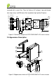
Main items of the inverter: 1) Main housing of the inverter 2) Wiring box of the inverter 3) Mounting bracket 4) External cooling fans 5) LED indication lights 6) LCD display 7) Key buttons 8) DC switch: DC power on/off 9) AC switch: AC power on/off 8
Chapter 3 Installation Below is the installation procedure for the inverter. Please read carefully and install the product step-by-step. Before installation, please check that the following items are included in the package: Table 3-1 Main items No.
(1) M8 Expansion tubes 8 For mounting bracket (2) M8×25 assembling bolts 8 For mounting bracket (3) M6X12 screw 6 (4) M5X10 screw 8 (5) M5 flange nut 2 (6) Lifting eye nut M10 2 For lifting the main housing (7) OT type terminal 2 For ground connection (8) (9) Pre-insulated end ferrule for AC side Pre-insulated ferrule for DC side end For wiring box and main housing; 2 spare parts For mounting bracket and inverter, external ground connection For internal ground stud connection;
purchased. 3.
3.
2) Installation method (see Figure 3-2): Make sure that the mounting structure (wall, rack, etc) is suitable to support the inverter weight. Follow the mounting guidelines below: (a) If the location permits, install the inverter vertically. (b) If the inverter cannot be mounted vertically, it may be tilted backward by no lower than 15 degrees from horizontal. (c) Do NOT mount the inverter leaning forward. (d) Do NOT mount the inverter in a horizontal position (<15 degrees).
3) Installation space requirement (see Figure 3-3): The distances between the inverters or the surrounding objects should meet the following conditions: NOTICE: The spacing between two adjacently mounted inverters should be ≥1000mm (39.4 inches). Ensure that the air space around the inverter is well ventilated. ≥300mm (11.8in.) ≥500mm (19.7in.) ≥1000mm (39.4in.) ≥600mm (23.6in.
Figure 3-4 Dimensions of holes on the bearing surface (2) Drill holes at the marked positions with a 10mm (0.4in.) drill and put the M8 expansion tubes① into the holes; Fasten the mounting bracket② with the M8x25 assembling bolts③ in the accessory kit. Tool: Electric drill (Ф10mm/0.4in. head), No.
1 2 3 Figure 3-5 Secure the mounting bracket (3) Hang the inverter onto the mounting bracket as shown in Figure 3-6 and Figure 3-7; Lift mounting: Take out the lifting eye nut M10 (2pcs) from the accessory kit, and screw them on the bolts at the top of the inverter. Use sling rope or bar (inserted through both lifting eye nuts) to lift the inverter onto the bracket. The minimum angle between the two sling ropes should be less than 90 degrees.
2 people to mount the inverter due to the weight of the equipment.
(4) Install the wiring box ① Remove the cover plate at the bottom of the main housing. (see Figure 3-8) Tool: No.
Tool: No.2 Phillips head screwdriver ③Insert the wiring box to the main housing, and use M6x12 screws (4pcs) to attach the wiring box to the inverter housing. (see Figure 3-10) Tool: No. 10 Wrench, torque value of 2.8N.m Figure 3-10 Installation of the wiring box CAUTION: The total weight of the CPS SCA23/28KTL-DO series inverter is about 55kg (≈122 pounds). Please ensure the mounting is properly installed before hanging the the inverter on the bracket.
Figure 3-11 Fix the main housing and wiring box on the bracket (6) Attach the cover board shown in Figure 3-10 to the left side of the wiring box. (see Figure 3-12) Tool: No.2 Phillips head screwdriver, torque value of 1.2N.
(7) Optional - Install an anti-theft padlock when the installation is complete. The anti-theft padlock is used to prevent the inverter from being stolen when the equipment is installed outdoors.
3.3 Electrical installation The connection interface of CPS SCA23/28KTL-DO series inverter: DC INPUT 1 DC INPUT 2 AC OUTPUT COMM. PORT ANT. 4 5 WARNING: High touch current . Earth connection essential before connecting supply. 1 1 2 3 Figure 3-15 External connection ports PV1 + 6 PV1 6 PV2 + 6 PV2 6 L1 L2 L3 N 7 8 Figure 3-16 Internal connection points 1. Knockout holes for DC input cable, 1-1/4” or 1” 2. Knockout hole for AC output cable, 1-1/4” or 1” 3.
Choose the cables for inverters according to the following configuration table: Table 3-3 Cables specifications Position DC input (﹢/﹣) length (m) #12~10AWG PV cable Cable #10~6AWG AC Max. cable Cable 61 (#10AWG) #8AWG output cable 32 (#8AWG) recommended (L1/L2/L3/N/PE) RS485 UTP CAT-5e communication communication or cable 3106A) 23 3x#22~18AWG (eg.
3.3.1 DC connection 1) Working mode CPS SCA23/28KTL-DO series inverter has two PV input sections: DC Input-1 and DC Input-2. These two sections can work under “Parallel mode” or “Independent mode”. (see Figure 3-17) Under Parallel mode, the two PV input sections share one MPP Tracker; Under Independent mode, each PV input section works with one MPP Tracker.
terminal blocks, and tighten the wire terminals back on the terminal blocks with a torque value of 1.2N.m. Figure 3-18 Internal configuration of parallel mode 4. Set the selector switch on the LCD board (see Figure 3-19) to parallel mode.
Figure 3-19 Location of the PV connection mode selector switch Selector switch for 1-----independent mode PV connection 2-----parallel mode mode 2) DC fuse selection CPS SCA23/28KTL-DO inverters can be equipped with typical 12A (23kW Inverter) and 15A (28kW Inverter) DC fuses. Customers must verify that the appropriate fuses are used depending on the actual configuration PV strings. 1) Each independent string of DC input from the PV strings needs fuse protection.
3) DC cable connection To ensure the optimum performance of the inverter, please read the following guidelines before DC connection: (a) Confirm the DC configuration referring to Table 3-5 and ensure that the maximum open circuit voltage of the PV modules is lower than 1000 Vdc under any conditions; (b) Confirm that the PV strings for each MPPT of the inverter are of the same type and specification before connection. The number, orientation, and tilt of PV strings may differ for different applications.
1-1/4 or 1 inch through the holes. Then put the cables through the conduits inside the wiring box. (e) Crimp the DC cables with the attached pre-insulated end ferrule (16Pcs) by using the the crimping pliers. (see Figure 3-21) Tools: Diagonal pliers, wire stripping pliers, crimping pliers Figure 3-21 Set up the DC input cables (f) Connect the crimped DC cables to the terminal block on the circuit board and fasten the screws, as shown in Figure 3-22: Tools: 4mm (0.16in.) flat screwdriver Torque value: 1.
Figure 3-23 Take off the cover of the wiring box 2) Knock out the holes of the DC side and plug the suitable conduits of 1-1/4 or 1 inch through the holes. Then put the cables through the conduit inside the wiring box. 3) The inverter supports 3 kinds of cable connection on the AC side depending on the grouding connection method. The cable set-up procedures are illustrated below. Table 3-6 Necessary tools for cable set up No. Tools 1. 4mm (0.16in.) flat screwdriver 2. 8mm hex socket wrench 3.
External grounding point 1 2 L1 L2 L3 N 1.6 N-m 3 L1 L2 L3 N L1 L2 L3 N AC OUTPUT COMM. PORT WARNING: High touch current . Earth connection essential before connecting supply. Figure 3-24 AC output and ground cable connection (1) Connect the AC (L1, L2, L3, N) cables to the terminal block and the st ground cable to the grounding bar. (see the 1 graph in Figure 3-24) Set up the cables referring to Figure 3-25.
Pre-insulated end ferrule 4pcs OT type terminal,1pcs Core wire Pre-insulated end ferrule Core wire OT type terminal Figure 3-26 AC output and ground cable set up (3) Connect the AC (L1, L2, L3, N) cables to the terminal block and use the OT type terminal to connect the ground cable to the external rd grounding point at the bottom of the wiring box. (see the 3 graph in Figure 3-24) Set up the cables referring to Figure 3-27.
cables. If the cable of other gauge is selected, different pre-insulated end ferrule is needed and provided by the installers. 4) When the output of the inverter is connected to the grid, an AC circuit breaker is recommended to be installed to safely disconnect the inverter from the grid when overcurrent happens.
3.3.3 Communication connection CPS SCA23/28KTL-DO series inverter supports industry standard Modbus RS485 communication. 1. Communication board description PAR IND S401 ON OFF S402 Communication board P203 P204 P207 P208 P205 3 4 Figure 3-29 Communication board 2. Connectors and communication cards Item Picture ① Dry Configuration description Please see the section after the table for detailed contact information. communic ation port P205 ② USB N.O. N.C.
③/④ No. RS485 port 1 (RJ45 2 connector) 3 Colour Function White orange Orange White green 485+ N.C 485- P203, P204 4 5 Blue White blue 6 7 Green White brown 8 Brown ⑤ RS485 1 -----NC port 2 -----NC (5pin 3 -----RS485+ connector) N.C. N.C. N.C. COM N.
⑦Selector 1-----Independent mode switch for 2-----Parallel mode setting the PV connection mode S401 ① Dry contact communication: The inverter features an alarm function that opens or closes a dry contact on the communication board. (available both as contact normally open – N.O. – and as contact normally closed – N.C.), as shown below: N.O. N.C.
Dry contact communication Status in fault Status without fault port condition condition P205: N.O. — COM Closed Open P205: N.C. — COM Open Closed Connection Plan: You can connect a LED or other loads to indicate the operational status of the inverter, as shown in the following figure: (or L + Line circuit Breaker( 3 A) (or L N) - + N) - Line circuit Breaker( 3 A) COM COM N.C. N.C. N.O. N.O. COM COM N.C. N.C. N.O. N.O. COM COM N.C. N.C. N.O. N.O.
install an individual miniature circuit-breaker between the dry contact and the power distribution grid. Dry contact communication cable connection: a.) Knock out the holes for suitable cable conduits of 3/4 inch. b.) Put the dry contact communication cable through the cable conduit and inside the wiring box. c.) Use double-layer insulated cables. Strip the cables according to the following requirements.
d.) Connect wires to the terminal. Tool: 2 or 2.5mm flat screwdriver No. Cable Color Function 1 Red N.O. 2 Blue N.C. 3 Green COM Figure 3-33 Wire connection e.) Plug the cable terminal into the P205 connector.
② RS485 communication cable connection: 1 2 3 4 Figure 3-35 RS485 connection 1. Cable connection of RS485 communication: RJ45 connector 2. Cable connection of RS485 network communication: RJ45 connector 3. Cable connection of RS485 communication: 5 pin connector 4. Cable connection of RS485 network communication: 5 pin connector No. 1 2 3 4 5 6 7 8 39 Colour Function White orange Orange White green Blue White blue Green White brown Brown 485+ N.C 485N.C. N.C. N.C. COM N.
Figure 3-36 Crimp RJ45 connector on the RS485 and Ethernet cable 1 -----NC 2 -----NC 3 (Red)--------RS485+ 4 (Blue) -------RS4855 (Green)----- COM (1) (2) (1) RS485 communication of single inverter (2) RS485 network communication Figure 3-37 Fasten the cable terminal on the RS485 5 pin connector a.) Put the communication cable through the conduits inside the wiring box, and crimp the cable as shown in Figure 3-36 and Figure 3-37.
RS485 network connection: When the inverters are monitored via the RS485 communication, the unique RS485 address for each inverter can be set through the LCD interface. Up to 31 inverters can be connected together in the RS485 communication network. The Daisy-chain topology is recommended for the RS485 network connection, as shown in Figure 3-38. Other communication topologies, such as the star networks, are not recommended.
Chapter 4 Commissioning WARNING: Please follow the guidelines below before on-grid operation to eliminate possible dangers to ensure safety. 4.1 Commissioning Checklist 4.1.1 Mechanical installation Make sure that the mounting bracket is secure and all the screws have been tightened to the specified torque values. (Please refer to 3.2 Mechanical installation) 4.1.2 Cable connections Make sure that all cables are connected to the right terminals.
the PV array is sufficient, the LCD screen of inverter will light up. The inverter will then start up with the message “sys checking”. 4.) Set up the grid standard: INSTRUCTION: Please check with your local electricity supply company before selecting the grid standard. If the inverter is operated with a wrong grid standard, the electricity supply company may cancel the operation license.
Figure 4-2 Select grid standard 5.) When the LCD screen shows the normal operation status (Figure 4-3) and the “RUN” light on the LED panel lights up, it indicates that the grid connection and power generation are successful. PV1 725 V 38.5A PV2 720 V 31.9A 277 27.9 223.2 08/12 13:10:05 277 22.9 183.7 08/12 13:10:10 (a) (b) Figure 4-3 Normal operation status 6.) If the inverter fails to operate normally, “FAULT” light will light up and the fault information will show on the LCD screen.
Chapter 5 User Interface 5.1 Description of LCD panel The inverter’s LCD panel mainly consists of LCD screen, LED indicator lights, buzzer and 4 keys, as shown in Figure 5-1. POWER RUN GRID FAULT Figure 5-1 LCD panel Interpretation for the indicator lights is shown in Table 5-1 and function of the keys is shown in Table 5-2.
operation on indication light Flash Light off Light Grid GRID status indication light on Flash Light off Light on FAULT Derated running status (light up 0.5s, light off 1.6s) In other operation status or power supply not working Grid is normal Grid fault (light up 0.5s, light off 1.6s) Power supply not working Indicates a Fault Fault Slow Indicates Alarm (light up 0.5s, light off status flash 2s) indication Fast Protective action (light up 0.5s, light light flash off 0.
Down Page down in selection menu/-1 when setting parameters 5.2 Operation state Table 5-1 indicates the definitions of LED, i.e. indicates the information of the inverter’s operation state. It indicates that the system is energized and under DSP control when “POWER” lights up. “RUN” will light up when the inverter detects that the grid connection conditions meet the requirements and power is fed into the grid.
Figure 5-2 LOGO interface (2) Indication of inverter operation mode: Sys.Checking >>>>>> Figure 5-3 Inverter system check ongoing Standby >>>>>> Figure 5-4 Inverter system in standby mode PV1 725 V 38.5A PV2 720 V 31.9A 277 27.9 223.2 08/12 13:10:05 277 22.9 183.
GridV.OutLim Figure 5-6 Fault indication interface LCD screen will display different mode interfaces based on the operation modes of the inverter. There are four operation modes: startup system check mode (as shown in Figure 5-3), stand-by mode (as shown in Figure 5-4), normal operation mode (as shown in Figure 5-5, the switching time between (a) and (b) is 5 seconds), and fault mode (as shown in Figure 5-6).
Figure 5-7 Main menus on the LCD screen The main operation interface of LCD screen has 5 menus, i.e. “1 OP. Info”, “2 Alarm”, “3 History”, “4 Setting” and “5 Dispatch”. The users may select options with UP and DOWN, and then press ENT to confirm selection. The users can return to the default indication interface by pressing ESC. 5.4.1 Operation information When the cursor moves to “1 OP. Info” in the main screen, you should press ENT to select the operation information as shown in Figure 5-8.
Remarks:The LCD display is shown as follows when PV parallel mode is selected. Upv Ipv 360.0V 14.7A Figure 5-9 Operation information indication (PV parallel mode) 5.4.2 Alarm As described before, if a fault occurs during normal operation of the inverter, corresponding fault messages will be indicated in “2 Alarm” menu in addition to the sound and light alarms. Move the cursor to “2 Alarm” and press ENT to check out the specific fault information, as shown in Figure 5-10.
History”: “1 HistErr”, “2 OP. Recd”, “3 Version” and “4 TotalTag”. (1) The error log can store up 100 fault messages in “1 HistErr” menu. (2) The last 21 days of operation history data is available to be checked in “2 OP. Recd” menu. All variable names in the data comply with the content in “1 OP. Info” menu of the main interface. The users can select the “2 OP. Recd” menu and input the retraceable days (For example, the input number is 21.
5.4.4 System configuration Move the cursor to “4 Setting” in the main interface. Press ENT to enter the password: UP -> DOWN -> UP -> DOWN. Press ENT to confirm, and set the current system parameters, as shown in Figure 5-12. There are 7 submenus in “4 Setting”: “1 ON/OFF”, “2 Language”, “3 Buzzer”, “4 SysTime”, “5 Commun.”, “6 OtherCmd” and “7 NetConfig”. → ON OFF ON State 4 Setting 1 ON/OFF 2 Language 3 Buzzer →4 SysTime 5 Commun 6 OtherCmd 7 NetConfig → 中文 English EnglishVer.
(1) The inverter can be started and shut down with “1 ON/OFF” menu. Move the cursor to “ON” and press ENT, “ON State” will then be indicated at the bottom of LCD screen; move the cursor to “OFF” and press ENT, then “OFF State” will be indicated as well. The inverter will stand by instead of working normally if the startup conditions do not meet the set value even if “ON” is selected. The inverter will be shut down immediately if “OFF” is selected in any case. (2) Five languages, i.e.
4. “MPPTCycle” is used to set up the cycle time of MPPT Scan. Move the cursor to this menu, press ENT to set up the cycle time. Use UP and DOWN to adjust the MPPT cycle time. Press ENT to confirm the setting. 5. “MPPTScan” is to execute the MPPT scanning manually. Move the cursor to this menu, and press ENT to initiate the scanning. The LCD screen will skip to normal operation interface if the MPPT scanning succeeds, but remain on the “MPPTScan menu” interface if the scanning fails.
5.4.6 AutoTest INSTRUCTION: Autotest is only needed for CEI 0-21 grid standard. The “6 Autotest” appears ONLY when users select the “CEI 0-21” grid standard. Users can do the Class I and Class II protection tests to the grid voltage and frequency by Class I and Class II protection tests. Select “6 Autotest” and press ENT to go to the 8 submenus, including “1 VMaxTest1”, “2 VMinTest1”, “3 FMaxTest1”, “4 FMinTest1”, “5 VMaxTest2”, “6 VMinTest2”, “7 FMaxTest2” and “8 FMinTest2”.
Inverter is NOT Running 1 OP.infor 2 Alarm 3 History 4 Setting 5 Dispatch 6 Autotest 1 VMaxTest1 2 VMinTest1 3 FMaxTest1 →4 FMinTest1 Select VolMax1Test Test Aborted! RadiationTooLow VMaxTest1 Start? Testing... UacMax1 Uac1 Uacoff1 Toff 5 VMaxTest2 6 VMinTest2 7 FMaxTest2 →8 FMinTest2 Select VolMin1Test VMinTest1 Start? Testing... UacMin1 Uac1 Uacoff1 Toff Select FreqMax1Test FMaxTest1 Start? FMinTest1 Start? 57 -- Hz -- Hz -- Hz -- mS Testing...
5.4.7 System protection parameters setup Press DOWN and ENT at the same time in the main interface and enter the password (UP -> DOWN -> UP -> DOWN) to access the system protection parameters setup menu. This menu includes 6 submenus: “1 SysPara”, “2 Restart”, “3 Recover”, “4 ClrErrRecd” and “5 Stdset”, as shown in Figure 5-15. 1 GridVProtect 2 GridFProtect 3 ON/OFF 4 PowerContr 5 LVRTSet 6 OtherProtect →1 SysPara.
INSTRUCTION: This function is effective only when the fault “IntFault0010~0150” in the troubleshooting table occurs. The inverter may restore to normal operation automatically if alarm or protection faults occur. This function will not respond when the inverter is in operation mode and a “FaultOperated” alarm interface will be indicated. (3) “3 Recover” menu: The manufacturer’s parameter default value can be restored when the inverter is not in operation mode. Otherwise “Fault Operated” will be reminded.
permitted. 5.4.8 System control parameters The “1 SysPara” menu has 6 submenus, including ”1 GridVProtect”, ”2 GridFProtect”, ”3 ON/OFF”, ”4 PowerContr”, ”5 LVRTSet” and ”6 OtherProtect”. (1) ”1 GridVProtect” and ”2 GridFProtect” menus: Set up the parameters of grid voltage, frequency protection and recovery, etc, as shown in Table 5-3: Table 5-3 Parameters of grid voltage and frequency (IEEE-1547) Parameter name GridV.Max1(V) VMaxTripT1(S) GridV.
Max. grid voltage GridVminRecT(V) GridVRecT(S) GridF.Max1(Hz) FmaxTripT1(S) GridF.Min1(Hz) FminTripT1(S) GridF.Max2(Hz) FmaxTripT2(S) Recovery threshold value of Min. grid voltage Recovery time of grid voltage protection Protection threshold value of Level 1 Max. grid frequency Trip time of Level 1 Max. grid frequency Protection threshold value of Level 1 Min. grid frequency Trip time of Level 1 Min. grid frequency Protection threshold value of Level 2 Max. grid frequency Trip time of Level 2 Max.
Threshold value of grid GridV.Unbal(%) {0.1, 2.6, 10.0} voltage unbalance (2) ”3 ON/OFF” menu: Set up the start-up and shut-down control parameters. Table 5-4 Start-up and turn-off control parameters Setup range (lower limit, Parameter name Description PVStartVol(V) PV start-up voltage {300.0, 330.0, 400.0} SoftStep(KW/S) Soft step {0.01, 1.00, 2.00} SoftOffOption Soft turn off option {Ban, Ban, Enable} OffPStep(KW/S) Turn off power step {0.01, 1.50, 2.
1). None: No mode/disable reactive power mode 2). Dispatch: Remote power dispatch mode Note: The ActivePower, PF and Q value can be adjusted by remote software if the “Dispatch” is selected. 3). QReactSet: Set the Q value Note: Change the reactive power by adjusting the Q value (reactive compensation) 4). PF Set: Set the PF value Note: Change the reactive power by adjusting the PowerFactor 5).
Note: The reactive compensation changes according to the grid voltage change, as shown in Figure 5-18. INSTRUCTION: The Q(U) curve function is only available for CEI 0-21 and IEEE-1547 grid standards. Q(%) (QuCurveU2i,QuCurveQ2i) Inductive + (QuCurveU1, QuCurveQ1) (QuCurveU1i, QuCurveQ1i) _ U(V) Capacitive (QuCurveU2,QuCurveQ2) Figure 5-18 Q(U) curve mode The Table 5-5 lists the parameters of QReactSet, PF Set, PF(P) Curve and Q(U) Curve modes.
PFCurvePF1 (-0.800, 1.000, 0.800) See Figure 5-17 PFCurveP2(%) (0, 100.0%, 100.0%) See Figure 5-17 PFCurvePF2 (-0.800, -0.900, 0.800) See Figure 5-17 PFCurvTripV(V) (480.0, 480.0, 528.0) PFCurveReV(V) (422.4, 432.0, 480.0) QuCurveU1(V) (480.0, 518.4, 528.0) See Figure 5-18 QuCurveQ1(%) (-100.0%, 0.0%, 100.0%) See Figure 5-18 QuCurveU2(V) (480.0, 528.0, 528.0) See Figure 5-18 QuCurveQ2(%) Q(U) (-100.0%, -50.0%, 100.
Table 5-6 Protection parameters of LVRT control Parameter name LVRTProtect LVRTVoltLimit(%) LVRTPosCurrK LVRTNegCurrK Description LVRT protection enable/disable LVRT voltage limit LVRT positive current K LVRT negative current K Setup range (lower limit, default & upper limit) {Ban, Enable1,Enable2} {70.0,80.0,90.0} {0,1.5,10.0} {0,2.0,10.
Chapter 6 Operation 6.1 Start-up Manual start-up: Manual start-up is required after regulation setting or manual (fault) shut-down. Move the cursor from the main operation interface to “4 Setting”. Press ENT and go to submenu “1 ON/OFF”. Then move the cursor to “ON” and press ENT to start the inverter. Then the inverter will start up and operate normally if the start-up condition is met. Otherwise, the inverter will go to stand-by mode.
Sys.Checking >>>>>> Figure 6-1 System self check ongoing This mode indicates that the inverter is checking whether it is ready for normal operation after the manual start-up of inverter. (2) Normal operation mode: Default indication interface for normal operation is shown in Figure 6-2 (a) and 6-2 (b). The switching time between (a) and (b) is 5 seconds. PV1 = PV2 480 = 480 VAC 6.0 kW ~ 80.2 kwh 08/12 13:10:10 VAC 400 V 6.0 kW 15.1 A ~ 80.2 kwh 08/12 13:10:05 480 V 12.
Standby >>>>>> Figure 6-3 Inverter system in standby mode (4) Fault mode, as shown in Figure 6-4: The inverter will disconnect from the power grid and turn into fault mode when the inverter or power grid fails. Check the specific cause in “Troubleshooting table” (Table 7-2) according to the fault message displayed on the LCD and eliminate the fault referring to the instructions.
PV array has adequate energy. After all conditions are met, the inverter will enter grid-tied power generation mode. While in grid-tied power generation, the inverter can detect the power grid at all times, and also keep the photovoltaic array output in maximum power point tracking (MPPT) mode. In case of any abnormity, the inverter will enter the protection program immediately.
Chapter 7 Maintenance and De-installation 7.1 Fault shut down and troubleshooting 7.1.1 LED fault and troubleshooting Please refer to the definition of LED lights in Table 5-1 and troubleshoot according to Table 7-1: Table 7-1 Trouble shooting of LED lights LED fault status Solutions Neither the “Power” LED nor the 1. Turn off the external AC LCD screen lights up. breaker 2. Switch the DC switch to “OFF” position 3. Check the PV input voltage and polarity The “GRID” LED is blinking. 1.
overfrequency / underfrequency, high environmental temperature or internal malfunction of the machine. The fault information will be displayed on the LCD screen. Please refer to “5.4.2 Present fault” for detailed operation. The causes of a fault can be identified based on the faults listed in Table 7-2. Proper analysis is recommended before contacting after-sales service. There are 3 types of fault: alarm, protection and hardware fault.
will be eliminated automatically; 2.Switch off 3-phase working power supply and then reboot the system; 3.Contact after-sales service personnel Definition: Cooling fan failure by visual check Possible causes: 1.Fan is blocked; 2.Fan service life has expired; 3. Fan socket connecter has poor contact. 3.ExtFanErr Recommended solutions: 1.Observe for 5 minutes and see whether the alarm will be eliminated automatically; 2.Check for foreign objects on fan blades; 3.
1.Ambient temperature outside the inverter is too high; 2.Fan is blocked; 3. Convection airflow is insufficient due to improper installation. Recommended solutions: 1.Confirm that external ambient temperature is within the specified range of operating temperature; 2.Check whether air inlet is blocked; 3.Check whether fan is blocked; 4.Check whether the location of installation is appropriate or not; 5.Observe for 30 minutes and see whether the alarm will be eliminated automatically; 6.
and power grid is disconnected or has any fault; 4.Contact after-sales service personnel Definition: Grid voltage frequency is abnormal, or power grid is not detected Possible causes: 1.Grid frequency is abnormal; 2.Cable connection between the inverter and the grid is poor; 3.GridF.OutLim Recommended solutions: 1.Observe for 10 minutes and see whether the alarm will be eliminated automatically; 2.Check whether the grid frequency is within the specified range; 3.
4.Contact after-sales service personnel Definition: PV module is connected inversely Possible causes: PV positive pole and negative pole are connected 5.PV1 (2) Reverse** inversely; Recommended solutions: 1.Check whether positive pole and negative pole are connected inversely; 2.Contact after-sales service personnel Definition: System leakage current is too high Possible causes: 1.Excessive parasitic capacitance on PV module due to environmental factor; 2.Grounding is abnormal; 6.GFCI.Err 3.
Recommended solutions: 1.Observe for 10 minutes and see whether the alarm will be eliminated automatically; 2.Check insulation of PV system; 3.Contact after-sales service personnel Definition: ARC fault Possible causes: Protection actions of ARC board 8.ARC Protect Recommended solutions: 1. Use “ARCFaultClear” to clear the ARC fault. (Refer to section 5.4.4) 2. Check if there is an arc in PV input or the connection of PV cable is not good. 2.
Protection procedure occurs inside the inverter Recommended solutions: 1.Observe for 10 minutes and see whether the alarm will be eliminated automatically; 2.Contact after-sales service personnel Definition: Internal fault of the inverter Possible causes: Fault occurs inside the inverter Fault IntFault0010~0150 Recommended solutions: 1.The inverter can be forced to restart once if it is required by operation and if it is confirmed that there is no other problem; 2.
7.2 Product maintenance 7.2.1 Check the electrical connection Check all the cable connections as a regular maintenance inspection every 6 months or once a year. 1.) Check the cable connections. If loose, please tighten all the cables referring to “3.3 Electrical installation”. 2.) Check for cable damage, especially whether the cable surface is scratched or smooth. Repair or replace the cables if necessary. 7.2.2 Clean the air vent filter The inverter can become hot during normal operation.
1 2 3 4 5 80
6 50~60mm mm 50~60mm mm Figure 7-1 Replace cooling fans 81
7.2.4 Replace the inverter Please confirm the following things before replacing the inverter: (1) The inverter is turned off. (2) The DC switch of the inverter is turned to OFF position. Then Replace the inverter according to the following steps: a.) Unlock the padlock if it is installed on the inverter. Figure 7-2 Unlock the padlock b.) Use a No.2 Phillips head screwdriver to unscrew the 2 screws on both sides of the inverter.
c.) Use a No. 10 Hex wrench to remove the 4 screws between the main housing and the wiring box. Lift up the main housing and disconnect from the wiring box. Figure 7-4 Disconnect the main housing from the wiring box d.) Use a No.2 Phillips head screwdriver to remove the 2 screws on the left side of the wiring box, and take off the cover board. Put the board on the connector of wiring box. Torque value: 1.2N.
7.3 De-installing the inverter De-install the inverter according to the following steps when the service time is due or for other reasons: DANGER: Please disconnect the electrical connection in strict accordance with the following steps. Otherwise, the inverter will be damaged and the service personnel’s life will be endangered. 1.) Turn off the AC breaker, and use Padlocks if provided. 2.) Turn off the DC breaker, and use Padlocks if provided. (Skip the two steps if there are no circuit breakers.) 3.
Chapter 8 Technical Data Model Name CPS SCA23KTL-DO/US-480 CPS SCA28KTL-DO/US-480 31kW 38kW 24kW 29kW DC Input Max. PV Power Nominal DC Input Power 1 Max. DC Input Voltage Operating DC Input Voltage Range Start-up DC Input Voltage / Power Number of MPP Trackers 2 MPPT Voltage Range Max. Input Current (Imp) Max.
Power Factor >0.99 (±0.8 adjustable) Current THD <3% AC Disconnection Type Load rated AC switch System Topology Transformerless Max. Efficiency 98.4% CEC Efficiency Stand-by / Night Consumption Environment 98.0% <20W / <2W Protection Degree NEMA 4 Cooling Operating Temperature Range Operating Humidity Variable speed cooling fans -13°F to +140°F / - 25°C to +60°C (derating from +113°F / +45°C) 0-95%, non-condensing 13123.4ft / 4000m (derating from 6561.
Note 1: When the DC input voltage is lower than 400V or higher than 800V, the inverter begins derating, as shown in Figure 8-1: Po/Pn 100% 80% 60% 40% 20% 300 500 (480) 800 900 1000 PV Voltage (V) Figure 8-1 SCA23/28KTL derating curve of PV input voltage Note 2: When the ambient temperature is higher than 113℉ (45℃), the output power begins derating, as shown in Figure 8-2: Po/Pn 100% 80% 60% 55% 40% 20% 113℉ (45℃) 140℉ (60℃) Tamb Figure 8-2 SCA23/28KTL derating curve with high temperature 87
Note 3: When the altitude is higher than 6562ft (2000m), the operating temperature of the inverter needs derating, as shown in Figure 8-3: Tamb (60℃) 140℉ (45℃) 113℉ 6562ft (2000m) 13123ft (4000m) Altitude Figure 8-3 SCA23/28KTL derating curve with high altitude Note 4: The inverter can output the AC power with full loads under 90%~110% of the rated grid voltage. When the grid voltage is lower than 90%, the output current will be limited within the allowable Max. current.
Chapter 9 Limited Warranty The warranty policy of this product is specified in the contract; otherwise, the warranty period is 5 years. For service, Chint Power Systems America will provide local support. For Warranty terms, please refer to the CPS America standard warranty policy in place at time of purchase.
Appendix: Instruction of inverter selection Table A-1 Optional accessory Item Standard Options Number ■CPS SCA23/28KTL-DO/US-480 inverter Note 1 □ DC SPD 1 □ DC and AC SPD 1 The following figure shows the wiring box equipped with the optional components: DC SPD AC SPD The position of the optional communication card Figure A-2 Internal structure of CPS SCA23/28KTL-DO inverter with optional components 90
CHINT POWER SYSTEMS AMERICA CO., LTD. Address: 700 International Parkway Suite 102 Richardson TX 75081 Web: www.chintpower.com/na Email: americasales@chintpower.com Service Hotline: 855-584-7168 SHANGHAI CHINT POWER SYSTEMS CO., LTD. All rights reserved. Specifications and designs included in this manual are subject to change without notice. CHINT POWER 2013/12-MKT PN: 9.0020.