
User Guide

6
IMPORTANT! If recovering Class A2, A2L, or A3 refrigerants, read ADDITIONAL SAFETY INSTRUCTIONS
ON PAGE 3 OF THIS MANUAL.
TO MINIMIZE RECOVERY TIME:
A. Use shortest length 1/4” (Inside Diameter) Refrigeration Hose on Suction Side of Recovery Unit.
B. Use an evacuated DOT Tank (90lb or larger, and rated for 550 PSI/38 Bar).
C. If refrigerant is clean, remove all suction side filters, screens, etc.
D. Remove all Schrader type valve cores and any valve depressors from hoses and service valves.
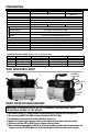
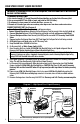
CONNECT RECOVERY UNIT (See Diagram 2)
• Use a Refrigerant Manifold (with sight glass) and two spare hoses.
• Connect Ground Strap between Recovery Unit and Recovery Tank (to prevent static electricity build
up).
1.
Connect Manifold
between A/C or Refrigeration unit being serviced and
Recovery Unit
IN
port.
2.
Connect Refrigerant
Hose from Recovery Unit OUT port to evacuated DOT
Recovery Tank
LIQUID
Valve
.
3.
Connect
another Refrigerant Hose from DOT Tank Vapor Port to Vapor Port of unit being serviced.
4.
OPEN
both Vapor and Liquid valves on DOT Recovery Tank.
5. Keep Manifold Valves
CLOSED
at this time.
6. On Recovery Unit, set
Main Power Switch
to
ON
.
7. Once Recovery Unit has started,
OPEN
LOW Side Manifold Valve to start liquid refrigerant flow to
Recovery Unit. Monitor liquid refrigerant flow in Manifold Sight Glass.
Note: Recovery Unit is designed to directly recover large amounts of liquid refrigerant. During Vapor
Recovery, if compressor makes slugging or hammering noise, meter incoming liquid refrigerant by
closing LOW Side Manifold Valve until noise subsides.
8. Once liquid refrigerant is no longer present in Manifold Sight Glass,
CLOSE
DOT Recovery Tank Vapor
Valve. This will transition Recovery Unit into Direct Vapor Recovery.
9. Let Recovery Unit run continuously. When desired vacuum level is observed on Low Side Manifold
Gauge, close both LOW & HIGH side Manifold Valves.
CAUTION: For Class A2, A2L and A3 recovery,
Recovery Unit must be turned OFF when 0 Psig to prevent possible ingestion of air during recovery
process.
10. If pressure on LOW Side Manifold Gauge starts to rise, open LOW Side Manifold Valve and restart
Recovery Unit. If LOW side manifold gauge remains in a vacuum, close all tank, manifold and hose
valves.
11. Remove discharge hose from Recovery Unit OUT Port. Recovery and Self-Clearing are now complete.
HIGH SPEED DIRECT LIQUID RECOVERY
Refrigerant
Manifold Set
A/C System
being serviced
Refrigerant
Recovery
Unit
Optional Tank Overfill Sensor Cord
From OUT Port To
Tank Liquid Valve
High Capacity Charging Scale
Hose From Dot Recovery Tank Vapor Port To A/C System Vapor Port
Optional Tank
Overfill Switch
DOT Recovery
Tank
A/C System
Being Serviced
DOT Recovery
Tank
Ground
Strap*
IN
IN
OUT
LIQUID
VAPOR
Diagram 2 - High Speed Direct Liquid Recovery
* Must be bare metal to bare metal contact.