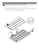
MODEL#: TM GFS483478 GFS603278 GFS603678 ® READ THE INSTRUCTIONS CAREFULLY Familiarize yourself with all the parts as shown in the exploded view. The exploded view will also provide a helpful reference when relating to the location of the various parts and how they are mounted. COPY THE MODEL NUMBER FOR YOUR RECORDS HERE # *Shown with Optional Corner and Edge Trim Please visit us on YouTube and view our Jetcoat® Wall System installation videos. One may be available for your installation. www.
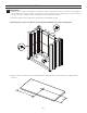
OPTIONAL 1 OPTIONAL 2 3 4 3 OPTIONAL 1 3 4 OPTIONAL 2 CAUTION: Do not set on corners when handling wall pieces. NOTE: Optional Corner and Edge Trim pieces are provided in the kit but are not necessary to complete the application of the JETCOAT® Shower Wall System. Read through the instruction manual in its entirety to understand how the wall panels can be installed to fit over your existing walls.
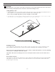
PARTS LIST 1 2 OPTIONAL Corner Trim 3 OPTIONAL Edge Trim 4 Tongue & Groove Panel 5 Beveled Edge Panel Double-Sided Construction Tape RECOMMENDED TOOLS 1 2 Utility Knife 5 3 Locking Pliers 6 Rubber Mallet BACKER BOARD STUD NAILING FLANGE SHOWER BASE Construction Grade Adhesive 7 Flathead Screwdriver SHOWER WALL 4 8 Circular Saw Silicone 9 Hole Saw Measuring Tape NOTE: SHOWER BASE INSTALLATION When used in conjunction with a shower base that has a nailing flange, the Jetcoat
PREPARATION TIPS Before beginning installation of product, make sure all parts are present. Compare parts with package contents list. If any part is missing or damaged, do not attempt to assemble or install the product. MASONITE: • Surface must be completely clean. This includes but not limited to: Soap scum, dust and any other contaminates that may affect adhesion. • Begin by measuring the overall width of the back wall after it has been cleaned and prepared for installation.
INSTALLATION PROCEDURE / STEP 1 1 MEASURING 1. Measure the height of installation area at both ends of each wall. From top of tub or shower pan to the ceiling. If the ceiling height is less than the height of the panels included in your kit, the panels can be cut down using the same cutting procedure outlined in Step 2. 2. Measure width of each wall at top and bottom of installation area. Important Note: Steps 2 &3 will be repeated when installing each of the 5 wall panels. 3.
INSTALLATION PROCEDURE / STEP 2 2 CUTTING Important Note: The arrows on the label on the back of each panel indicate the TOP of the Panel. The following cutting instructions should be used when making all cuts. Cutting Panels to Size: 1. Carefully draw a line on the back of each panel where the cut is to be made. Any adjustments for out of square or out of plumb should be considered when drawing this line. Note: Using a straight edge when possible is highly recommended 2.
INSTALLATION PROCEDURE / STEP 3 3 APPLYING ADHESIVE AND TAPE TO BACK SIDE OF WALL PANELS The following instructions should be used when applying tape and adhesive to each wall panel. 1. Apply double-sided construction tape to the back of the wall panel as shown. 2. Apply construction grade adhesive to the spaces between the tape as shown in a circular pattern. The beads of adhesive should be 2" apart and up to, but no closer than 1" from the panel edge.
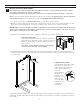
INSTALLATION PROCEDURE / STEP 4 4 INSTALL LEFT BACK WALL PANEL Important Note: Failure to install the back wall panels in the correct order may cause the pattern across the back wall not to appear continuous. Important Note: The arrows on the label on the back of each panel indicate the TOP of the Panel. Note: Your kit contains 3 back wall panels (labeled on the back as (3) First Panel, (3) Second Panel and (3) Third Panel) and two end panels (labeled (4) Right Panel & (4) Left Panel). 1.
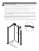
INSTALLATION PROCEDURE / STEP 5 5 INSTALL BACK CENTER WALL PANEL Important Note: The arrows on the label on the back of each panel indicate the TOP of the Panel. 1. Locate the panel labeled (3) Second Panel and lay it down on a flat surface. 2. Based on your measurements from Step 1 (Measuring) trim the height, if necessary, and make any required plumbing cut-outs according to the instructions in Step 2 (Cutting). 3. Apply the double-sided tape and construction adhesive as explained in Step 3. 4.
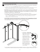
INSTALLATION PROCEDURE / STEP 6 6 INSTALL BACK RIGHT WALL PANEL Important Note: The arrows on the label on the back of each panel indicate the TOP of the Panel. 1. Locate the panel labeled (3) Third Panel and lay it down on a flat surface. 2. Based on your measurements from Step 1 (Measuring) cut the panel to the appropriate size and make any required plumbing cut-outs according to the instructions in Step 2 (Cutting).
INSTALLATION PROCEDURE / STEP 7 7 INSTALL LEFT WALL PANEL Important Note: The arrows on the label on the back of each panel indicate the TOP of the Panel. 1. Locate the panel labeled (4) Left Panel and lay it down on a flat surface. 2. Based on your measurements from Step 1 (Measuring) cut the panel to the appropriate size and make any required plumbing cut-outs according to the instructions in Step 2 (Cutting).
INSTALLATION PROCEDURE / STEP 8 8 INSTALL RIGHT SIDE WALL PANEL Important Note: The arrows on the label on the back of each panel indicate the TOP of the Panel. 1. Lay (4) Right Panel down on a flat surface. 2. Based on your measurements from Step 1 (Measuring) cut the panel to the appropriate size and make any required plumbing cut-outs according to the instructions in Step 2 (Cutting).
INSTALLATION PROCEDURE / FINISHING 9 OPTIONAL: INSTALL EDGE TRIM 1. Measure and cut (2) Edge Trim for length and to cover tile or existing wall material as needed. 2. Fill the channel that the wall panel will slide into with caulk and apply construction grade adhesive to the back of the Edge Trim piece. Carefully position the Edge Trim and push it into place. 2 2 10 CAULK CORNERS AND EDGES 3 Properly caulk around the Jetcoat® Shower Wall System to insure a secure fit and finish.
® TM LIMITED WARRANTY FGI Industries, Ltd., warrants to the original purchaser that this JETCOAT® Shower Wall System kit will be free of manufacturing defects, which affect its performance as a bathing or showering fixture, under the following conditions and subject to the limitations contained in the “Remedies” and “Warranty Limitations” sections. Please go here to register: USA: www.craftandmain.com CANADA: www.craftandmain.
MODELO NÚM.: TM GFS483478 GFS603278 GFS603678 ® LEE DETENIDAMENTE LAS INSTRUCCIONES Familiarízate con todas las piezas tal como se muestran en la vista ampliada. La vista ampliada sirve también como útil referencia para conocer la ubicación de varias piezas y cómo se instalan.
OPCIONAL 1 OPCIONAL 2 3 4 3 OPCIONAL 1 3 4 OPCIONAL 2 CUIDADO: No colocar sobre esquinas al manipular piezas de pared NOTA: Se proporcionan piezas opcionales de molduras de esquina y borde en el kit, pero no son necesarias para completar la instalación del sistema de pared de ducha JETCOAT®. Lee todo el manual de instrucciones para comprender cómo pueden instalarse los paneles de pared a fin de ajustarlos sobre las paredes existentes.
LISTA DE PIEZAS 1 2 OPCIONAL Moldura de esquina 3 OPCIONAL Moldura de borde 4 5 Panel con borde biselado Panel con lengüeta y ranura Cinta adhesiva de doble cara para uniones de estructuras HERRAMIENTAS RECOMENDADAS 1 2 Cuchillo multiuso 5 7 Destornillador plano TABLERO DE RESPALDO PARED DE DUCHA VIGA BRIDA DE CLAVADO BASE PARA DUCHA 4 Adhesivo para construcción Tenazas de bloqueo 6 Martillo de goma 3 8 Sierra circular Silicona 9 Sierra cilíndrica Cinta de medir NOTA: INSTA
CONSEJOS DE PREPARACIÓN Antes de instalar el producto, asegúrate de tener todas las piezas. Compara las piezas con la lista de contenido del paquete. Si alguna pieza falta o está dañada, no intentes ensamblar o instalar el producto. MASONITA: • La superficie tiene que estar completamente limpia. Esto incluye, aunque no se limita a: Sedimentos de jabón, polvo y otros contaminantes que pueden afectar la adherencia.
PROCEDIMIENTO PARA LA INSTALACIÓN / PASO 1 1 CÓMO MEDIR 1. Mide la altura del área de instalación en ambos extremos de cada pared. Desde la parte superior de la bañera o plato de la ducha hasta el techo. Si la altura del techo es menor que la altura de los paneles incluidos en el kit, los paneles se pueden cortar usando el mismo procedimiento de corte descrito en el Paso 2. 2. Mide el ancho de cada pared en la parte superior e inferior del área de instalación.
PROCEDIMIENTO PARA LA INSTALACIÓN / PASO 2 2 CÓMO CORTAR Nota importante: Las flechas en la etiqueta en la parte posterior de cada panel indican la PARTE SUPERIOR del panel.Las siguientes instrucciones de cómo cortar deben usarse al hacer todos los cortes. Cortar los paneles a la medida: 1. Traza con cuidado una línea en la parte posterior de cada panel donde se realizará el corte. Se debe considerar cualquier ajuste por falta de escuadra o plomada al trazar esta línea.
PROCEDIMIENTO PARA LA INSTALACIÓN / PASO 3 3 CÓMO APLICAR ADHESIVO Y CINTA ADHESIVA A LA PARTE POSTERIOR DE LOS PANELES DE PARED Se deben usar las siguientes instrucciones al aplicar cinta y adhesivo a cada panel de pared. 1. Aplica cinta adhesiva de construcción de doble cara en la parte posterior del panel de pared como se muestra. 2. Aplica adhesivo para construcción en los espacios entre la cinta tal como se muestra en un patrón circular. Las líneas de adhesivo deben estar a 2" (5.
PROCEDIMIENTO PARA LA INSTALACIÓN / PASO 4 4 INSTALA EL PANEL DE PARED POSTERIOR IZQUIERDO Nota importante: No instalar los paneles de la pared trasera en el orden correcto puede hacer que el patrón a lo largo de la pared trasera no parezca continuo. Nota importante: Las flechas en la etiqueta en la parte posterior de cada panel indican la PARTE SUPERIOR del panel.
PROCEDIMIENTO PARA LA INSTALACIÓN / PASO 5 5 INSTALA EL PANEL TRASERO DE PARED CENTRAL Nota importante: Las flechas en la etiqueta en la parte posterior de cada panel indican la PARTE SUPERIOR del panel. 1. Localiza el panel etiquetado (3) segundo panel y colócalo sobre una superficie plana. 2. Según las medidas del Paso 1 (Medición), recorta la altura, si es necesario, y haz los cortes para la plomería necesarios de acuerdo con las instrucciones del Paso 2 (Corte). 3.
PROCEDIMIENTO PARA LA INSTALACIÓN / PASO 6 6 INSTALA EL PANEL TRASERO DE PARED DERECHA Nota importante: Las flechas en la etiqueta en la parte posterior de cada panel indican la PARTE SUPERIOR del panel. 1. Localiza el panel etiquetado (3) tercer panel y colócalo sobre una superficie plana. 2. Según las medidas del Paso 1 (Medición), corta el panel al tamaño apropiado y haz los cortes de plomería necesarios de acuerdo con las instrucciones del Paso 2 (Corte).
PROCEDIMIENTO PARA LA INSTALACIÓN / PASO 7 7 INSTALA EL PANEL DE PARED LATERAL IZQUIERDO Nota importante: Las flechas en la etiqueta en la parte posterior de cada panel indican la PARTE SUPERIOR del panel. 1. Localiza el panel etiquetado (4) panel izquierdo y colócalo sobre una superficie plana. 2. Según las medidas del Paso 1 (Medición), corta el panel al tamaño apropiado y haz los cortes de plomería necesarios de acuerdo con las instrucciones del Paso 2 (Corte).
INSTALLATION PROCEDURE / STEP 8 8 PROCEDIMIENTO PARA LA INSTALACIÓN / PASO 8 Nota importante: Las flechas en la etiqueta en la parte posterior de cada panel indican la PARTE SUPERIOR del panel. 1. Coloca (4) el panel derecho sobre una superficie plana. 2. Según las medidas del Paso 1 (Medición), corta el panel al tamaño apropiado y haz los cortes de plomería necesarios de acuerdo con las instrucciones del Paso 2 (Corte).
PROCEDIMIENTO DE INSTALACIÓN / ACABADO: 9 OPCIONAL: CÓMO INSTALAR LA MOLDURA DE BORDE 1. Mide y corta (2) molduras de borde a lo largo y cubre las baldosas o material de pared existente según sea necesario. 2. Llena el canal en el que se deslizará el panel de pared con pasta selladora y aplica adhesivo de grado de construcción en la parte posterior de la moldura de borde. Coloca con cuidado la moldura de borde y empújala en su lugar.
® TM GARANTÍA LIMITADA FGI Industries, Ltd., warrants to the original purchaser that this JETCOAT® Shower Wall System kit will be free of manufacturing defects, which affect its performance as a bathing or showering fixture, under the following conditions and subject to the limitations contained in the “Remedies” and “Warranty Limitations” sections. Para registrarse, visite: USA: www.craftandmain.com CANADA: www.craftandmain.
MODÈLE Nº : TM ® GFS483478 GFS603278 GFS603678 LISEZ LES INSTRUCTIONS ATTENTIVEMENT Familiarisez-vous avec toutes les pièces illustrées dans la vue éclatée. La vue éclatée servira également de référence utile pour l’emplacement des différentes pièces et la façon dont elles sont installées. COPIEZ LE NUMÉRO DE MODÈLE ICI POUR VOS DOSSIERS *Illustré avec Garniture de coin et de rebord en option Veuillez nous rendre visite sur YouTube et regarder nos vidéos d’installation de la cabine murale Jetcoat®.
EN OPTION 1 EN OPTION 2 3 4 3 EN OPTION 1 3 4 EN OPTION 2 ATTENTION : Ne posez pas sur les coins lorsque vous manipulez les pièces murales. REMARQUE : Les pièces de garniture de coin et de garniture de rebord en option sont fournies avec le prêt-à-monter mais ne sont pas nécessaires pour terminer l’installation de la cabine de douche JETCOAT®.
LISTE DES PIÈCES 1 EN OPTION Garniture de coin 2 3 4 EN OPTION Garniture de rebord Panneau à languette et rainure 5 Panneau à rebord biseauté Ruban double face de construction OUTILS RECOMMANDÉS 1 2 Couteau universel 5 3 Pince-étau 6 Maillet en caoutchouc PLANCHE D’APPUI PAROI DE CABINE DE DOUCHE MONTANT BRIDE DE CLOUAGE BAC DE DOUCHE Adhésif de qualité construction 7 Tournevis à tête plate 4 8 Scie circulaire Silicone 9 Scie-cloche Ruban à mesurer REMARQUE : INSTALLATION
CONSEILS PRATIQUES DE PRÉPARATION Avant de procéder à l’installation du produit, assurez-vous qu’il ne manque aucune pièce. Vérifiez que toutes les pièces de la liste du contenu de l’emballage sont bien présentes. Si l’une des pièces est manquante ou endommagée, ne tentez pas d’assembler ou d’installer le produit. • Commencez par mesurer la largeur totale du mur arrière, une fois qu’il est nettoyé et préparé pour l’installation.
PROCÉDURE D’INSTALLATION/ÉTAPE 1 1 PRISE DE MESURES 1. Mesurez la hauteur de la surface d’installation aux deux extrémités de chaque mur. À partir du haut de la baignoire ou du bac de douche et jusqu’au plafond. Si la hauteur du plafond est inférieure à celle des panneaux compris dans votre prêt-à-monter, les panneaux peuvent être raccourcis à l’aide de la procédure de coupe décrite à l’étape 2. 2. Mesurez la largeur de chaque mur en haut et en bas de la surface d’installation.
PROCÉDURE D’INSTALLATION/ÉTAPE 2 2 COUPER Remarque importante : Les flèches figurant sur l’étiquette au dos de chaque panneau indiquent le HAUT du panneau. Il faut suivre les instructions de coupe suivantes pour toutes les coupes. Couper les panneaux à la bonne taille : 1. Tracez une ligne avec soin au dos de chaque panneau, là où la coupe sera effectuée. Tout ajustement pour un mur qui n’est pas d’équerre ou mal aplombé doit être envisagé quand vous tracez cette ligne.
PROCÉDURE D’INSTALLATION/ÉTAPE 3 3 APPLIQUER L’ADHÉSIF ET LE RUBAN ADHÉSIF AU DOS DES PANNEAUX MURAUX Les instructions suivantes doivent être suivies quand vous posez le ruban adhésif et l’adhésif sur chaque panneau mural. 1. Appliquez le ruban double face de qualité construction au dos de la surface murale comme illustré. 2. Appliquez l’adhésif de qualité construction sur les zones entre le ruban adhésif comme illustré selon un tracé circulaire.
PROCÉDURE D’INSTALLATION/ÉTAPE 4 4 INSTALLATION DU MUR ARRIÈRE GAUCHE Remarque importante : Une installation des panneaux muraux arrière dans l’ordre incorrect peut résulter en un aspect discontinu de la paroi arrière assemblée. Remarque importante : Les flèches figurant sur l’étiquette au dos de chaque panneau indiquent le HAUT du panneau.
PROCÉDURE D’INSTALLATION/ÉTAPE 5 5 INSTALLATION DU PANNEAU MURAL ARRIÈRE DU MILIEU Remarque importante : Les flèches figurant sur l’étiquette au dos de chaque panneau indiquent le HAUT du panneau. 1. Repérez le panneau étiqueté (3) Second panneau et couchez-le sur une surface plane. 2. En fonction de vos prises de mesure à l’étape 1 (Prise de mesures), raccourcissez la hauteur au besoin, et effectuez toutes les découpes de plomberie requises, conformément aux instructions de l’étape 2 (Couper). 3.
PROCÉDURE D’INSTALLATION/ÉTAPE 6 6 INSTALLATION DU PANNEAU MURAL ARRIÈRE DROIT Remarque importante : Les flèches figurant sur l’étiquette au dos de chaque panneau indiquent le HAUT du panneau. 1. Repérez le panneau étiqueté (3) Troisième panneau et couchez-le sur une surface plane. 2. En fonction de vos prises de mesure à l’étape 1 (Prise de mesures), coupez le panneau aux dimensions appropriées et effectuez toutes les découpes de plomberie requises, conformément aux instructions de l’étape 2 (Couper).
PROCÉDURE D’INSTALLATION/ÉTAPE 7 7 INSTALLATION DU PANNEAU MURAL LATÉRAL GAUCHE Remarque importante : Les flèches figurant sur l’étiquette au dos de chaque panneau indiquent le HAUT du panneau. 1. Repérez le panneau étiqueté (4) Panneau gauche et couchez-le sur une surface plane. 2. En fonction de vos prises de mesure à l’étape 1 (Prise de mesures), coupez le panneau aux dimensions appropriées et effectuez toutes les découpes de plomberie requises, conformément aux instructions de l’étape 2 (Couper).
PROCÉDURE D’INSTALLATION/ÉTAPE 8 8 INSTALLATION DU PANNEAU MURAL LATÉRAL DROIT Remarque importante : Les flèches figurant sur l’étiquette au dos de chaque panneau indiquent le HAUT du panneau. 1. Couchez le (4) Panneau droit sur une surface plane. 2. En fonction de vos prises de mesure à l’étape 1 (Prise de mesures), coupez le panneau aux dimensions appropriées et effectuez toutes les découpes de plomberie requises, conformément aux instructions de l’étape 2 (Couper).
PROCÉDURE D’INSTALLATION/FINITION 9 EN OPTION : INSTALLATION DE LA GARNITURE DE REBORD 1. Mesurez et coupez la (2) Garniture de rebord à la bonne longueur et de façon à recouvrir les carreaux ou le matériau mural existant, selon les besoins. 2. Remplissez de calfeutre la rainure dans laquelle le panneau mural glissera, et appliquez un adhésif de qualité construction au dos de la garniture de rebord. Positionnez la garniture de rebord avec soin et poussez-la en place.
® TM GARANTIE LIMITÉE FGI Industries, Inc., garantissent à l’acheteur initial que cette cabine de douche JETCOAT® sera exempte de tout défaut de fabrication qui nuirait à son rendement en tant que qu’unité de bains ou de douche, dans les conditions suivantes et sous réserve des restrictions figurant dans les sections « Recours » et « Exclusions de garantie ». Veuillez vous rendre sur le site suivant pour vous inscrire : USA: www.craftandmain.com CANADA: www.craftandmain.