CX505 6” x 89” EDGE BELT SANDER User Manual
TABLE OF CONTENTS General Safety Instructions .......................................................................... 3 Specific Safety Instructions........................................................................... 4 Features ....................................................................................................... 5 Physical Features ......................................................................................... 6 Unpacking ................................................
GENERAL SAFETY INSTRUCTIONS Extreme caution should be used when operating all power tools. Know your power tool, be familiar with its operation, read through the owner’s manual and practice safe usage procedures at all times. ALWAYS read and understand the user manual before operating the machine. router bits, shaper heads, blades, knives or making other adjustments or repairs. CONNECT your machine ONLY to the matched and specific power source. NEVER leave a tool unattended while it is in operation.
CX505 – 6” x 89” EDGE BELT SANDER SPECIFIC SAFETY INSTRUCTIONS MAKE SURE the sander is connected to the matched and specific power source instructed in the manual. ALL THE GUARDS must be in place while operating the sander to ensure safety. MAKE SURE before making any adjustments, the switch is in the “OFF” position and the cord is un-plugged from the power source. NEVER sand more than one work piece at a time on this sander. ALWAYS wear a dust mask and safety glasses while operating the sander.
CX505 FEATURES MODEL CX505 – 6” x 89” EDGE BELT SANDER As part of the growing line of Craftex CX-Series woodworking equipment, we are proud to offer CX505 a 6” x 89” Edge Belt Sander. By following the instructions and procedures laid out in this user manual, you will receive years of excellent service and satisfaction. The CX505 is a professional tool and like all power tools, proper care and safety procedures should be adhered to. Motor ...................................
CX505 – EDGE BELT SANDER PHYSICAL FEATURES Belt Guard Belt Tension Lever 6” x 48” Sanding Belt Dust Hood Lock Knobs Fence Lock Knobs Motor Drum Guard Fence Work Table 4” Dust Hood Sanding Head Tilt Lock Knob 1-1/2 HP Motor Cabinet Door Lock ON/OFF Switch Cabinet Door Cabinet Powdered Coated Paint 6
UNPACKING The machine is properly packaged and shipped completely in crate for safe transportation. When unpacking, carefully inspect the crate and ensure that nothing has been damaged during transit. SETUP The unpainted surfaces of the tables are coated with a protective coating which prevents rust. Clean this protective coating using a rag with kerosene or painter thinner before starting assembling the machine.
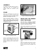
ASSEMBLY Assembling the CX505 edge belt sander is simple and easy. To assemble the machine, follow the instructions given below. STAND Attach the side brackets to the front and rear brackets as shown in figure-2 using screws and washers and lock washers provided. Do not tighten the screws. Attach the brackets together as shown in figure-2 using screws, washers and lock washers provided. Make sure the stand is sitting level on the floor from all four sides and tighten the screws.
FENCE Slide two T-nuts into the T-slot on the table and place the fence on the table aligning the two slots on the fence with the two holes on the T-nuts. Secure fence to the table using washers and lock knobs. Figure-5 Securing the sander onto the stand from inside the cabinet WARNING! The CX505 is a heavy machine. Do not over-exert yourself. Get the help of an assistant when lifting the sanding head onto the stand.
Insert the rod into the hole as shown in figure-9 making sure that the flat surface of the rod is facing the hole on the bracket. Use the knob provided, and secure the rod in position. IMPORTANT The dust hood can not be properly closed when the table is installed on the sander. In order to use dust hood with your sander, uninstall the table whenever the table is not being used. WORKPIECE STOP Loosen the knob securing the dust hood in position and move the dust hood out of the way.
Proper belt tracking prolongs the belt life, preventing the belt from slipping off the drums during operation. The belt tracking is adjusted by tilting the idler drum slightly towards the front or rear of the machine. ON/OFF SWITCH To check the belt tracking: The ON/OFF switch on CX505 features a safety key to prevent from accidental or unauthorized operations. When the sander is not in use for a long period of time, simply insert the safety key into the switch.
TEST RUN Once you have assembled your machine completely, it is then time for a test run to make sure that the machine works properly and is ready for operation. Before starting the sander for a test run make sure you have performed the belt tracking adjustment (see page-10) so that the belt does not come off the drums or jam against the sander during startup.
WARNING! Make sure the machine’s power switch is off and the cord is disconnected from the power source when installing/removing any part or servicing the sander. TILTING THE SANDING HEAD The sanding head can be adjusted to any angle from 90° to 180° as required for your job. To tilt the sanding head: TABLE HEIGHT ADJUSTMENT The table on CX505 can be adjusted to different heights.
INSTALLING / REPLACING SANDING BELT The CX505 comes with a 6”x 89” sanding belt. To install the sanding belt: Make sure the machine is disconnected from the power source. Uninstall the belt guards, dust hood, auxiliary table and the work-piece stop (if already installed). Figure-17 Belt tension handle Once the belt is installed, perform the belt tracking adjustment so that the belt tracks in the center of the drums.
MAINTENANCE During the life of your machine, you will need to practice some regular maintenance to keep your sander in peak performance condition. WARNING! Make sure the machine’s power switch is OFF and the cord is disconnected from the power source when installing / removing any part or servicing the sander. Check your machine daily for the following before use: CLEANING The moisture from the wood dust remaining on the table surface can cause rust.
TROUBLESHOOTING TROUBLE Motor doesn’t start. Sanding belt slips. Machine vibrates excessively. CAUSES 1. No electricity. 2. Defective switch, motor or cord. 3. Overload has reacted. 1. Sanding belt is stretched. 2. Too much applied pressure. 1. Stand on uneven floor. 2. Motor mounts are loose. Abrasive belt keeps tearing. 1. Belt is running the wrong direction. Sanded edge not square. 1. Table not square to sanding platen. Sanding marks on the wood. 1. Work piece was held still. 2.
CX505 PARTS DIAGRAM 17
CX505 PARTS LIST REF NO. IVM 1 20101001 CABINET 1 2 W0000006 MAGANETIC SWITCH 1 8 20101005 WORK TABLE BRACK 1 9 S0120380 LOCK NUT 3/8"-16UNC 1 10 20101007 CAM ECCENTRIC 1 10A S0110600 HEX. NUT 3/8"-16UNC 1 11 S0310525 PIN 5*25 1 12 10102024 LOCK HANDLE 3/8"-16UNC 1 13 10102023 HAND KNOB 1 14 S0400525 KEY 5*5*25 1 15 S0020416 HEX. HD. SCR. 1/4"*20UNC*1" 1 16 S0210404 FLAT WASHER 1/4"*23 5 17 DESCRIPTION 20101011A TABLE QTY 1 17A S0020510 CAP SCR.
25 S0310306 PIN 3*6 1 26 S0050404 SET SCR. 1/4"*20UNC*1/4" 1 27 10104049Q POSITION PLATE 1 28 10104050 POINTER 1 28A 20102020 LOCKING NUT 1 29 20101022 SANDING BELT 1 30 10104046 MITER GAUGE BODY 1 31 S0030108 RD.HD.SCR. 5/32"*32UNC*1/2" 3 32 S0110100 HEX.
51 20101031 BELT REPLACING PLATE 1 54 20101032a SAND CLAMP HANDLE 1 55 S0020530 HD.HEX.SCR. 5/16"*18UNC*1-3/4" 1 56 S0120201 NYLON NUT 5/16"-18UNC 5 57 20101033 TILT SCALE 1 58 S0040301c FLAT HD.SCR. 3/16*3/4 1 59 10102022 WIDTH POINTER 1 60 S0040300 FLAT HD.SCR. 3/16"*24UNC*3/8" 1 61 M0000000 MOTOR 1 62 S0020520 HD.HEX.SCR 5/16"*18UNC*1-1/4" 5 63 S0210500 FLAT WASHER 8.
81 20103044 DRIVER WRENCH 1 82 S0040512M FLAT HD.SCR. M5 8 83 S0040420M FLAT HD.SCR. 4*20 8 87 S0121400M ANTI-LOOSEN NUT M14*2.0P 1 88 10401029 RUBBER FEET 4 89 S0090512 RD.HD.SCR 5/16"-18*3/4" 4 90 90100062 FIXED BASE 2 94 20101051 EXTENSION TABLE 1 95 S0230300 SPRING WASHER 3/16" 96 20101050 SUPPORTING ROD 1 100 J0000102 SCALE 1 101 10105052 LABEL 1 103 S0010505 HEX. SCREW 5/16" * 1-1/4" 2 104 S0030501 HEX.
143 21700029 EXTENSION SPRING 1 144 C1100698 SMALL BALL BEARING 3 145 S0520008 RING 1 146 21700025 FIXED LOOP 2 S0010520M SOC. HD. CAP SCR. 5*20 4 147 148 20900049 BEARING COVER 6202 1 149 S0020501 HEX. HD. SCREW 5/16"*18UNC*1" 1 150 S0040412M FLAT HD. SCREW 4*12 3 151 21700017 BEARING BASE 1 152 C1206202 BEARING 6202 1 154 20900049 BEARING COVER 6202 1 155 C1106003 BEARING 6003 1 159 S0400430 KEY 1 161 21700015 FIXED BASE 1 162 S0010510M HEX.
179 21700051 ROLLER ARBOR 1 183 21700008 DRIVEN ROLLER 1 184 S0050606M SOC.SET.SCR.
WARRANTY CRAFTEX 3 YEARS LIMITED WARRANTY Craftex warrants every product to be free from defects in materials and agrees to correct such defects where applicable. This warranty covers three years for parts and 90 days for labour (unless specified otherwise), to the original purchaser from the date of purchase but does not apply to malfunctions arising directly or indirectly from misuse, abuse, improper installation or assembly, negligence, accidents, repairs or alterations or lack of maintenance.