READ THESE INSTRUCTIONS AND SAVE THEM FOR FUTURE USE Installation Guide For Models: BW248AG6 BW248SS6 E192641 net weight of fan: 27.58 lb (12.51 kg) Table of Contents: Safety Tips. pg. 1 Unpacking Your Fan. pg. 2 Parts Inventory. pg. 2 Installation Preparation. pg. 3 Hanging Bracket Installation. pg. 3 Fan Assembly. pgs. 4 - 5 Wiring. pg. 6 Canopy Assembly. pg. 7 Light Kit Assembly (Optional). pgs. 7 - 8 Alternate Final Assembly, Without Light Kit. pg. 8 Automated Learning Process./ Activating Code.
SAFETY TIPS. WARNING: To reduce the risk of electrical shock, turn off the electricity to the fan at the main fuse box or circuit panel before you begin the fan installation or before servicing the fan or installing accessories. 1. READ ALL INSTRUCTIONS AND SAFETY INFORMATION CAREFULLY BEFORE INSTALLING YOUR FAN AND SAVE THESE INSTRUCTIONS. CAUTION: To avoid personal injury, the use of gloves may be necessary while handling fan parts with sharp edges. 2.
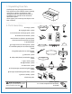
1. Unpacking Your Fan. Carefully open the packaging. Remove items from Styrofoam inserts. Remove motor assembly and place on carpet or Styrofoam to avoid damage to finish. Do not discard fan carton or Styrofoam inserts should this fan need to be returned for repairs. Check against parts inventory that all parts have been included. 2. Parts Inventory. a c b a. canopy. 1 piece b. hanging bracket. 1 piece c. 4½in. downrod and hanging ball. 1 piece d. remote control receiver. 1 piece d f e g e.
To prevent personal injury and damage, ensure that the hanging location allows the blades a clearance of 10 feet (3.05m) from the floor and 30in. (76 cm) from any wall or obstruction. This fan is suitable for room sizes up to 400 square feet (37.2 square meters). 12ft. - 20ft. (3.66m - 6.1m) 3. Installation Preparation. blade edge 30 10 feet inches (3.05m) (76cm) 12ft. - 20ft. (3.66m - 6.1m) downrod installation This fan can be mounted with a downrod on a regular (no-slope) ceiling only.
. Fan Assembly. If you wish to extend the hanging length of your fan, you must remove the hanging ball from the 4½in. downrod provided to use with an extended downrod (sold separately). [If you wish to use the 4½in. downrod, please proceed to instructions following the dotted line below.] set screw hole set screw stop pin hanging ball To remove hanging ball, loosen set screw on hanging ball, lower hanging ball and remove stop pin.
5. Fan Assembly. (cont.) With the hanging bracket secured to the outlet box and able to support the fan, you are now ready to hang your fan. Grab the fan firmly with two hands. Slide downrod through opening in hanging bracket and let hanging ball rest on the hanging bracket. Turn the hanging ball slot until it lines up with the hanging bracket tab.
Las modificaciones no aprobadas por la parte responsable de la conformidad podrían invalidar la autorización del usuario para manejar el equipo. 6. Wiring. *NOTA: Se han hecho pruebas en este equipo y se ha comprobado que cumple con los límites para un aparato digital de clase B, de acuerdo con la Parte 15 de las Reglas de la FCC. Se concibieron estos límites para proveer protección razonable contra la interferencia adversa en una instalación residencial.
antenna 7. Canopy Assembly. hanging bracket Locate 2 screws on underside of hanging bracket and remove screw closest to the open end of the hanging bracket. Partially loosen the other screw. Lift canopy to hanging bracket. Place rounded part of slotted hole in canopy over loosened screw in hanging bracket and push up. Twist canopy to lock. Re-insert screw that was removed and then tighten both screws securely.
8. Light Kit Assembly (Optional). (cont.) Remove finial and finial plate from threaded rod at bottom of light kit fitter. Raise glass shade in order to align threaded rod on light kit fitter with hole in middle of glass shade and push up gently, allowing threaded rod to come through hole. Replace finial plate and finial that were previously removed. Secure glass shade to light kit fitter by tightening finial. Do NOT overtighten finial as glass may crack or break.
. Automated Learning Process./ Activating Code. transmitter (back) CAUTION: The remote control transmitter can be programmed to multiple receivers or fans. If this is not desired, turn wall switch off to any other programmable receiver or fan. code switches Remove battery cover on back side of remote control transmitter. Use a ballpoint pen or a small screwdriver to set the code switches 1 through 4 for the transmitter.
12. Remote Control Operation. HI button - turns the 2 smaller fans to HIGH speed MED button - turns the 2 smaller fansto MEDIUM speed LOW button - turns the 2 smaller fans to LOW speed button - turns the 2 smaller fans OFF button - turns light ON/OFF when tapped quickly. Pressing and holding button down for more than 0.7 seconds converts it into a dimmer. button - turns main fan ON/OFF when pressed once (i.e., controls ROTATION of the ENTIRE fan) 13. Testing Your Fan.
Troubleshooting. Warranty. WARNING: Failure to disconnect power supply prior to troubleshooting any wiring issues may result in serious injury.