
Installation guide


page 6
6. Wiring.
CAUTION: Be sure outlet box is properly grounded
and that a ground wire (GREEN or Bare) is present.
Make sure all electrical connections comply with Local
Codes or Ordinances and the National Electrical Code
(or Canadian Electrical Code). If you are unfamiliar
with electrical wiring or if the house/building wires are
different colors than those referred to in the diagram
to the right, please use a qualified electrician.
WARNING: If using this fan in a DAMP location, this
fan must be connected to a supply circuit that is
protected by a Ground Fault Circuit Interrupter
(GFCI) to reduce the risk of personal injury, electrical
shock or death.
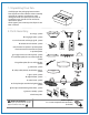
When downrod is secured in place on the hanging
bracket, wire the RECEIVER with wire connectors
provided as shown in diagram at right.
Tip: While you are wiring, keep in mind that wires
must not obstruct receiver from sliding into
hanging bracket.
* Wrap each wire connector separately with
electrical tape as an extra safety measure.
Gently insert receiver (flat side up) into hanging
bracket and carefully push wires and taped wire
connectors into outlet box. Let antenna rest outside
of hanging bracket.
(wiring for receiver)
IN ORDER TO WIRE WALL CONTROL, remove existing
wall switch. Wire the WALL CONTROL with wire
connectors provided as shown in diagram at right.
* Wrap each wire connector separately with electrical
tape as an extra safety measure. Gently push wires
and taped wire connectors into outlet box.
Use a ballpoint pen or a small screwdriver to set the
code switches 1 through 4 on the wall control. Factory
setting is pre-set and not recommended for use. Write
down number sequence for use in Section 10.
NOTE: Because this fan requires compact fluorescent
bulbs, the dimmer switch (labeled D and X) has been
pre-set to the "OFF" position (X). [Most compact
fluorescent bulbs, including the ones provided with
this fan, are not compatible for use with dimmer
controls.]
Attach wall control to outlet box and secure with
screws from original wall switch. Attach front plate to
wall control using 2 screws provided in the wall
control.
(wiring for wall control)
white supply wire
black supply wire
black
black
white
grey
blue
blue
grey
white
from receiver
black
AC IN L
AC IN N
white
white
ground (green
or bare)
from fan
from receiver
antenna
from ceiling
black
receiver
ground (green
or bare)
green
black
(AC IN from
breaker box)
black (TO POWER supply)
black
green/
green/
bare
bare
ground
ground
green/
bare
ground
outlet box
wall
control
plate
1
2
3
4
X
D
code
switches
black (OUT to fan)
black (OUT to fan)
black (OUT to fan)
dimmer
switch
Las modificaciones no aprobadas por la parte responsable de la conformidad
podrían invalidar la autorización del usuario para manejar el equipo.
*NOTA: Se han hecho pruebas en este equipo y se ha comprobado que cumple con los límites para un
aparato digital de clase B, de acuerdo con la Parte 15 de las Reglas de la FCC. Se concibieron estos
límites para proveer protección razonable contra la interferencia adversa en una instalación residencial.
Este equipo produce, usa y puede radiar energía de radiofrecuencia y, si no se instala y no se usa según
las instrucciones, puede causar interferencia adversa en la radiocomunicación. Sin embargo, no hay
ninguna garantía de que no habrá interferencia en una instalación en particular. Si este equipo sí causa
interferencia adversa en la recepción de radio o televisión, que se puede determinar apagando y
prendiendo el equipo, se le urge al usuario a intentar rectificar la interferencia tomando una o más de
las medidas que siguen:
* Orientar la antena de nuevo o localizarla en otro sitio.
* Aumentar la separación entre el equipo y el receptor.
* Conectar el equipo a un tomacorriente en un circuito distinto al cual está
conectado el receptor.
Solicitar ayuda del distribuidor o un técnico de radio/televisión.