READ THESE INSTRUCTIONS AND SAVE THEM FOR FUTURE USE . ly O . P F. t On men e c Pla r o F Installation Guide For Models: BW321AG3 BW321SS3 Table of Contents: Safety Tips. pg. 1 Unpacking Your Fan. pg. 2 Parts Inventory. pg. 2 Installation Preparation. pg. 3 Hanging Bracket Installation. pg. 3 Fan Assembly. pgs. 4 - 5 Wiring. pgs. 5 - 6 Canopy Assembly. pg. 6 Automated Learning Process/ Activating Code. pg. 7 Wall Control Operation. pg. 7 Remote Control Operation. pg. 8 Testing Your Fan. pg.
SAFETY TIPS. WARNING: To reduce the risk of electrical shock, turn off the electricity to the fan at the main fuse box or circuit panel before you begin the fan installation or before servicing the fan or installing accessories. 1. READ ALL INSTRUCTIONS AND SAFETY INFORMATION CAREFULLY BEFORE INSTALLING YOUR FAN AND SAVE THESE INSTRUCTIONS. CAUTION: To avoid personal injury, the use of gloves may be necessary while handling fan parts with sharp edges. 2.
1. Unpacking Your Fan. Carefully open the packaging. Remove items from Styrofoam inserts. Remove motor assembly and place on carpet or Styrofoam to avoid damage to finish. Do not discard fan carton or Styrofoam inserts should this fan need to be returned for repairs. Check against parts inventory that all parts have been included. 2. Parts Inventory. a. canopy. 1 piece a b c d e f i j b. hanging bracket. 1 piece c. 4½in. downrod and hanging ball. 1 piece d. remote control receiver. 1 piece e.
12ft. - 20ft. (3.66m - 6.1m) 3. Installation Preparation. blade edge To prevent personal injury and damage, ensure that the hanging location of the fan allows the fan cage a clearance of 10 feet (3.05m) from the floor and that the edges of the fan cage will be at least 30in. (76 cm) from any wall or obstruction. This fan is suitable for room sizes up to 400 square feet (37.2 square meters). This fan can be mounted with a downrod on a regular (no-slope) ceiling ONLY.
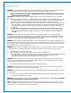
. Fan Assembly. If you wish to extend the hanging length of your fan, you must remove the hanging ball from the 4½in. downrod provided to use with an extended downrod (sold separately). [If you wish to use the 4½in. downrod, please proceed to instructions following the dotted line below.] set screw hole set screw stop pin hanging ball To remove hanging ball, loosen set screw on hanging ball, lower hanging ball and remove stop pin.
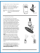
5. Fan Assembly. (cont.) With the hanging bracket secured to the outlet box and able to support the fan, you are now ready to hang your fan. Grab the fan firmly with two hands. Slide downrod through opening in hanging bracket and let hanging ball rest on the hanging bracket. Turn the hanging ball slot until it lines up with the hanging bracket tab.
6. Wiring. (cont.) IN ORDER TO WIRE WALL CONTROL, remove existing wall switch. Wire the WALL CONTROL with wire connectors provided as shown in diagram at right. outlet box * Wrap each wire connector separately with electrical tape as an extra safety measure. Gently push wires and taped wire connectors into outlet box. wall control green/ green/ bare bare ground ground 1 2 3 4 green black Use a ballpoint pen or a small screwdriver to set the code switches 1 through 4 on the wall control.
. Automated Learning Process./ Activating Code. CAUTION: The remote control transmitter can be programmed to multiple receivers or fans. If this is not desired, turn wall switch off to any other programmable receiver or fan. TRANSMITTER (back) Use a ballpoint pen or a small screwdriver to set the code switches 1 through 4 for the transmitter. Use the same number sequence used when wiring the wall control in Section 6 (page 6). Install 9-volt battery (included) in transmitter.
10. Remote Control Operation. HI button - turns lower fan to HIGH speed MED button - turns lower fan to MEDIUM speed LOW button - turns lower fan to LOW speed OFF button - turns lower fan OFF main fan button - turns main fan ON/OFF when pressed once (i.e., controls ROTATION of the ENTIRE fan) lower fan 11. Testing Your Fan. It is recommended that you test fan before finalizing installation. Restore power from circuit box and light switch (if applicable).
Warranty. Troubleshooting. CRAFTMADE/ELLINGTON LIFETIME WARRANTY: CRAFTMADE/ELLINGTON warrants this fan to the original household purchaser for indoor use under the following provisions: 1-YEAR WARRANTY: CRAFTMADE/ELLINGTON will replace or repair any fan which has faulty performance due to a defect in material or workmanship. Contact Craftmade/Ellington Customer Service at 1-800-486-4892 to arrange for return of fan. Return fan, shipping prepaid, to Craftmade/Ellington.
LEER ESTAS INSTRUCCIONES Y GUARDARLAS PARA UTILIZACION FUTURA . ly O . P . F ent On cem a l P For Guía de instalación Para modelos: BW321AG3 BW321SS3 3170356 peso neto del ventilador: 7,09 kg (15,63 lb) Indice de materias: Sugerencias de seguridad. Pág. 1 Desempaquetado del ventilador. Pág. 2 Inventario de piezas. Pág. 2 Preparación para la instalación. Pág. 3 Instalación del soporte de montaje. Pág. 3 Ensamblaje del ventilador. Págs. 4 - 5 Instalación eléctrica. Págs.
SUGERENCIAS DE SEGURIDAD. ADVERTENCIA: Para evitar la posibilidad de una descarga eléctrica, desconectar la corriente en la caja de fusibles principal o el interruptor protector antes de iniciar la instalación del ventilador o antes de repararlo o instalar accesorios. 1. LEER TODAS LAS INSTRUCCIONES E INFORMACIÓN DE SEGURIDAD CUIDADOSAMENTE ANTES DE INSTALAR SU VENTILADOR Y GUARDAR ESTAS INSTRUCCIONES.
1. Desempaquetado del ventilador. Abrir el empaque cuidadosamente. Sacar los artículos del embalaje. Sacar la unidad del motor y ponerla en una alfombra o en el embalaje para evitar rayar el acabado. Guardar la caja de cartón o el empaquetamiento original en caso de que tenga que mandar el ventilador para alguna reparación. Comprobar las piezas del ventilador con el inventario de piezas y verificar que se incluyeron todas. 2. Inventario de piezas. a b c d e f i j a. cubierta decorativa. 1 unidad b.
3. Preparación para la instalación. borde del aspa Este ventilador SÓLO se puede colgar con el tubo en un techo regular (sin inclinación). NO SE PUEDE colgar el ventilador al ras con el techo NI en un techo abovedado. Se necesitan las herramientas siguientes para la instalación: Destornillador de estrella Phillips, destornillador de paleta (plano), alicates ajustables o llave de tuercas, escalera de tijera, cortaalambres y cinta aisladora.
5. Ensamblaje del ventilador. Si usted desea extender la longitud colgante del ventilador, usted tendrá que quitar la bola que sirve para colgar del tubo de 11,43cm provisto para usarla con un tubo más largo (a la venta por separado). [Si desea utilizar el tubo de 11,43cm, favor de pasar a las instrucciones después de la línea punteada corta más abajo.
5. Ensamblaje del ventilador. (cont.) viga de madera bucle del cable de seguridad Ya que esté sujetado el soporte de montaje a la caja de salida y capaz de apoyar el ventilador, usted está listo para colgar el ventilador. Agarrar el ventilador firmemente con las dos manos. Deslizar el tubo por la abertura del soporte de montaje y dejar que se detenga la bola en el soporte de montaje. Girar la bola que sirve para colgar hasta que la ranura de la bola se alinee con la parte saliente del soporte de montaje.
6. Instalación eléctrica. (cont.) PARA HACER LA INSTALACION ELECTRICA DEL CONTROL DE PARED, quitar el interruptor de pared existente. Alambrar el CONTROL DE PARED con los conectores para cable provistos así como se muestra en el diagrama al lado. caja de salida * Como una medida de seguridad adicional, envolver cada conector para cable con cinta aisladora. Delicadamente meter los cables y los conectores para cable que tienen cinta dentro de la caja de salida.
8. Proceso de aprendizaje automático./ El activar el código. PRECAUCION: Se puede programar el transmisor del control remoto para usar con varios receptores o ventiladores. Si no desea hacer esto, apagar el interruptor de cualquier otro receptor o ventilador programable. conmutadores de los códigos bolígrafo TRANSMISOR (parte de atrás) 1 Quitar la tapa de la batería en la parte de atrás del transmisor del control remoto.
10. Funcionamiento del control remoto. Botón HI - pone el ventilador inferior en velocidad ALTA Botón MED - pone el ventilador inferior en velocidad MEDIA Botón LOW - pone el ventilador inferior en velocidad BAJA Botón OFF - APAGA el ventilador inferior Botón - ENCIENDE/APAGA el ventilador principal cuando se oprime el botón una vez (es decir, controla la ROTACION del ventilador ENTERO) ventilador principal ventilador inferior 11. Verificación del funcionamiento del ventilador.
Localización de fallas. Garantía. ADVERTENCIA: El no desconectar el suministro de fuerza eléctrica antes de hacer localización de fallas para cualquier problema de instalación eléctrica puede causar lesiones graves.