Operator’s Manual LAWN TRACTORS WITH SMART LAWN TECHNOLOGY Model Nos. 247.27038*, 247.27042*, 247.27049*, 247.27039*, 247.27044*, 247.27055*, 247.27056*, 247.27048* & 247.27047* * -- Last digit of model number varies 5 6 Safe Operation Practices..................................................2 Slope Gauge....................................................................7 Assembly & Set-Up...........................................................8 Controls & Operation................................
SAFETY INSTRUCTIONS WARNING DANGER This symbol points out important safety instructions which, if not followed, could endanger the personal safety and/or property of yourself and others. Read and follow all instructions in this manual before attempting to operate this machine. Failure to comply with these instructions may result in personal injury. When you see this symbol, HEED ITS WARNING! This machine was built to be operated according to the safe operation practices in this manual.
SAFETY INSTRUCTIONS • Check overhead clearances carefully before driving under low hanging tree branches, wires, door openings etc., where the operator may be struck or pulled from the machine, which could result in serious injury. Do Not: • Do not turn on slopes unless necessary; then, turn slowly and gradually downhill, if possible. • Disengage all attachment clutches and depress the brake pedal completely before attempting to start engine.
SAFETY INSTRUCTIONS • On slopes, the weight of the towed equipment may cause loss of traction and loss of control. • Always use extra caution when towing with a machine capable of making tight turns (e.g. “zero-turn” ride-on mower). Make wide turns to avoid jack-knifing. • Travel slowly and allow extra distance to stop. • Do not coast downhill.
SAFETY INSTRUCTIONS DO NOT MODIFY ENGINE SPARK ARRESTOR To avoid serious injury or death, do not modify engine in any way. Tampering with the governor setting can lead to a runaway engine and cause it to operate at unsafe speeds. Never tamper with factory setting of engine governor.
SAFETY INSTRUCTIONS Symbol Description DANGER — SAFETY DEVICES Keep safety devices (guards, shields, switches, etc.) in place and working. BYSTANDERS Keep bystanders, helpers, children and pets at least 75 feet from the machine while it is in operation. WARNING— SLOPE OPERATION Do not operate this machine on a slope greater than 15 degrees. Do not mow across slopes. Mow up and down slopes no greater than 15 degrees. Avoid sudden turns. Use low speed.
SLOPE GAUGE (OK) Figure 1 15° Slope 15° e da s h e d lin USE THIS SLOPE GAUGE TO DETERMINE IF A SLOPE IS TOO STEEP FOR SAFE OPERATION! To check the slope, proceed as follows: 1. Remove this page and fold along the dashed line. 2. Locate a vertical object on or behind the slope (e.g. a pole, building, fence, tree, etc.) 3. Align either side of the slope gauge with the object (See Figure 1 and Figure 2 ). 4. Adjust gauge up or down until the left corner touches the slope (See Figure 1 and Figure 2). 5.
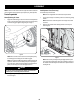
ASSEMBLY Install Operator’s Seat (If necessary) NOTE: All references in this manual to the left or right side and front or back of the tractor are from the operating position only. Exceptions, if any, will be specified. To install the seat proceed as follows: Tractor Preparation NOTE: The seat is shipped with the seat switch and seat pan attached. 1. Manually Moving the Tractor 1. Engage the transmission bypass rod to move the tractor manually without starting it.
ASSEMBLY 3. Lower Deck Discharge Chute Deflector Rotate the seat into position and secure the seat into place with the previously removed shoulder screws and flange lock nuts. Be careful not to crimp or damage the wire harness while installing the seat. See Figure 3. WARNING Never operate the mower deck without the chute deflector installed and in the down position. Check the mower deck for a shipping brace that may be holding the chute deflector upward for shipment.
ASSEMBLY Adjusting the Seat 1. WARNING Remove the plastic cover, if present, from the positive battery terminal and attach the red cable to the positive battery terminal (+) with the bolt and hex nut. See Figure 8. Before operating the tractor, make sure the seat is engaged in the seatstop. Engage the parking brake. Stand behind the machine and pull back on seat until it clicks into place. To adjust the position of the seat, lift the seat adjustment lever up.
ASSEMBLY b. Remove the front and rear deck wheels by removing the flange lock nuts and shoulder bolts that secure them to the deck. See Figure 9. 1. Be sure engine is outdoors and in a well-ventilated area. 2. Clean area around the fuel fill cap and remove the fuel fill cap. 3. Using an approved red GASOLINE container, add fuel slowly, being careful to avoid spilling. 4. Fill the tank until the fuel reaches the bottom of the fuel tank neck. 5. Replace the fuel cap and tighten securely.
OPERATION Fuel Tank Cap Throttle/Choke Control Lever Hour Meter Ignition Module Forward Drive Pedal Electric PTO Switch Brake Pedal Reverse Drive Pedal Park Brake/Cruise Control Lever Manual PTO Handle Storage Tray Deck Lift Lever Cup Holder Manual PTO Models Seat Adjustment Lever Transmission Bypass Rod Figure 10 Now that you have set up your riding mower, it’s important to become acquainted with its controls and features. Refer to Figure 10. NOTE: This Operator’s Manual covers several models.
OPERATION Throttle/Choke Control Lever Electric PTO (Blade Engage) Switch The throttle/choke control lever is located on the left side of the tractor’s dash panel. This lever controls the speed of the engine and, when pushed all the way forward, past the detent position closes the choke for cold starting. When set in a given position, the throttle will maintain a uniform engine speed. The PTO switch is located on the dash panel to the right of the LCD Service Minder & Hour Meter.
OPERATION Change Oil position, the PTO With the ignition key in the NORMAL MOWING clutch will automatically shut off if the PTO is moved into the ENGAGED (ON) position with the drive pedal in position for reverse travel. • The LCD will display the letters “CHG”, followed by the letters “OIL”, followed by the letters “SOON”, then finally followed by the meter’s accumulated time. “CHG/OIL/SOON/ TIME” will alternate on the display for 7 minutes after the meter reaches 50 hours.
OPERATION Reverse Caution Mode Driving The Tractor The REVERSE CAUTION MODE position of the ignition module allows the tractor to be operated in reverse with the blades (PTO) engaged. NOTE: Mowing in reverse is not recommended. WARNING Use extreme caution while operating the tractor in the REVERSE CAUTION WARNING Avoid sudden starts, excessive speed and sudden stops. 1. Lightly press the brake pedal to release the parking brake. Move the throttle into the FAST position. 2.
OPERATION Driving On Slopes To disengage the cruise control, lightly press the forward drive pedal or the brake pedal. Refer to the SLOPE GAUGE on page 8 to help determine slopes where you may operate the tractor safely. NOTE: Cruise control can not be set at the tractor’s fastest ground speed. If the operator should attempt to do so, the tractor will automatically decelerate to the fastest optimal mowing ground speed.
OPERATION Engaging the PTO (Manual PTO tractors) 7. When approaching the other end of the strip, slow down or stop before turning. Engaging the PTO transfers power to the cutting deck or other (separately available) attachments. To engage the PTO: 8. Align the mower with an edge of the mowed strip and overlap approximately 3”. 9. Direct the tractor on each subsequent strip to align with a previously cut strip. 1. Move the throttle to the FAST 10. 2.
SERVICE AND MAINTENANCE MAINTENANCE SCHEDULE WARNING Before performing any type of maintenance/service, disengage all controls and stop the engine. Wait until all moving parts have come to a complete stop. Disconnect spark plug wire and ground it against the engine to prevent unintended starting. Always wear safety glasses during operation or while performing any adjustments or repairs. Interval Follow the maintenance schedule given below. This chart describes service guidelines only.
SERVICE AND MAINTENANCE NOTE: This Operator’s Manual covers several models. Tractor features may vary by model. Not all features in this manual are applicable to all tractor models and the tractor depicted may differ from yours. WARNING 3. Place an appropriate oil collection container with at least a 2.5 quart capacity below the opening of the oil drain tube, to collect the used oil. Remove the oil fill cap/dipstick from the oil fill tube. 4.
SERVICE AND MAINTENANCE d. e. 6. 7. The engine is equipped with a twist-and-pull drain port. Turn the oil drain valve 1⁄4-turn counter-clockwise, then pull outward to begin draining oil. After the oil has finished draining, push the end of the oil drain valve back in and turn 1⁄4-turn clockwise to secure it back in place. Re-cap the end of the oil drain valve to keep debris from entering the drain port. 2. Disengage the PTO, set the parking brake and stop the engine. 3.
SERVICE AND MAINTENANCE Lubrication Deck Wheels WARNING Before lubricating, repairing, or inspecting, always disengage the PTO, set the parking brake, stop the engine and remove the key to prevent unintended starting. Front Wheels Each of the front wheel axles and rims is equipped with a grease fitting. See Figure 18 for the location of the grease fitting on the axles and Figure 19 for the location of the grease fitting on the rims. Lubricate with a No.
SERVICE AND MAINTENANCE 2. Measure the distance from the outside of the left blade tip to the ground and the distance from the outside of the right blade tip to the ground. Both measurements taken should be 4”. If they’re not, proceed to the next step. Leveling the Deck (Side-to-Side) 3. If the cutting deck appears to be mowing unevenly, a side to side adjustment can be performed.
SERVICE AND MAINTENANCE Relays and Switches Jump Starting WARNING Never jump start a damaged or frozen battery. Be certain the vehicles do not touch, and ignitions are off. Do not allow cable clamps to touch. 1. Connect positive (+) cable to positive (+)post of your tractor’s discharged battery. 2. Connect the other end of the cable to the positive (+) post of the jumper battery. 3. Connect the second cable negative (–) to the other post of the jumper battery. 4.
SERVICE AND MAINTENANCE e. Remove the bow-tie pin that secures the PTO cable to the bracket on the deck, pull back on the PTO cable, then slide it out of the bracket and unhook the spring from the idler bracket. See Figure 23. c. Working on the right side of the tractor, insert a 3⁄8” drive ratchet wrench, set to tighten, into square hole found on the idler bracket. See Figure 25. Insert Wrench Here Figure 23 f.
SERVICE AND MAINTENANCE 2. Use the wrench to pivot the deck drive pulley forward. See Figure 26. 8. WARNING CAUTION Avoid pinching injuries. Never place your fingers on the idler spring or between the belt and a pulley while installing the belt. 3. Carefully remove the belt from around the PTO pulley. 4. Looking at the cutting deck from the left side of the tractor, locate the bowtie pin on the rear left side of the deck. See Figure 27.
SERVICE AND MAINTENANCE 4. To properly sharpen the cutting blades, remove equal amounts of metal from both ends of the blades along the cutting edges, parallel to the trailing edge, at a 25°- to 30° angle. Always grind each cutting blade edge equally to maintain proper blade balance. See Figure 30. 2. Loosen, but do not remove the flange lock nut on the left idler pulley for 50” and 54” Decks and the right idler pulley for 42” and 46” Decks.
SERVICE AND MAINTENANCE Flange Lock Nut Figure 33 3. Figure 35 Carefully remove the belt from around the idler pulleys and the spindle pulleys. WARNING Avoid pinching injuries. Never place your fingers on the idler spring or between the belt and a pulley while removing the belt. 4. Route the new belt as shown in Figure 34 for 42” Decks, Figure 35 for 46” Decks and Figure 36 for 50” and 54” Decks.
SERVICE AND MAINTENANCE 8. Pull the right side of the belt and place the narrow V side of the belt into the PTO pulley. See Figure 37. Figure 37 9. While holding the belt and pulley together, rotate the pulley to the left. Continue holding and rotating the pulley and belt until the belt is fully rolled into the PTO pulley. Changing the Transmission Drive Belt Several components must be removed and special tools used in order to change the tractor’s transmission drive belt.
OFF-SEASON STORAGE WARNING Never store lawn tractor with fuel in tank indoors or in poorly ventilated areas where fuel fumes may reach an open flame, spark, or pilot light as on a furnace, water heater, clothes dryer, or gas appliance. PREPARING THE ENGINE WARNING Gasoline is a toxic substance. Dispose of gasoline properly. Contact your local authorities for approved disposal methods. IMPORTANT: Fuel left in the fuel tank during warm weather deteriorates and will cause serious starting problems.
TROUBLESHOOTING WARNING Before performing any type of maintenance/service, disengage all controls and stop the engine. Wait until all moving parts have come to a complete stop. Disconnect spark plug wire and ground it against the engine to prevent unintended starting. Always wear safety glasses during operation or while performing any adjustments or repairs. This section addresses minor service issues. To locate the nearest Sears Service Center or to schedule service, simply contact Sears at 1-888-331-4569.
Manual del Operador TRACTORES CORTACÉSPED AVEC INTELLIGENT TECHNOLOGIE CORTACÉSPED Modelo N.° 247.27038*, 247.27042*, 247.27049*, 247.27039*, 247.27044*, 247.27055*, 247.27056*, 247.27048* & 247.27047* * -- Último dígito del número de modelo varía 5 6 Medidas de Seguridad...........................................................32 Indicador de pendientes....................................................... 37 Armado e Instalación.............................................................
INSTRUCCIONES DE SEGURIDAD ADVERTENCIA PELIGRO La presencia de este símbolo indica que se trata de instrucciones de seguridad importantes que debe respetar para evitar poner en riesgo su seguridad personal y/o material y la de los demás. Lea y cumpla todas las instrucciones de este manual antes de intentar operar esta máquina. Si no respeta estas instrucciones puede provocar lesiones personales.
INSTRUCCIONES DE SEGURIDAD • El silenciador y el motor se calientan y pueden causar quemaduras. No los toque. No haga lo siguiente: • Revise la holgura superior antes de conducir debajo de ramas bajas, cables, cerramientos de puertas, etc., donde el operador puede golpearse o ser tirado de la máquina, lo que podría resultar en lesiones graves. • No gire en pendiente a menos que sea necesario; si lo hace, gire lenta y gradualmente cuesta abajo, si es posible.
INSTRUCCIONES DE SEGURIDAD • En las pendientes, el peso del equipo remolcado puede causar pérdida de tracción y pérdida de control. • Siempre tenga mucho cuidado al remolcar con una máquina capaz de hacer giros cerrados (por ejemplo, tractor cortacésped con radio de giro cero). Realice giros amplios para el acodillamiento. • Desplácese lentamente y deje distancia adicional para detenerse. • No baje las pendientes por inercia.
INSTRUCCIONES DE SEGURIDAD NO MODIFIQUE EL MOTOR AMORTIGUADOR DE CHISPAS Para evitar lesiones graves o la muerte, no modifique el motor de ninguna manera. Si altera la configuración del regulador, el motor se puede desbocar y funcionar a velocidades que no son seguras. Nunca cambie la configuración de fábrica del regulador del motor.
INSTRUCCIONES DE SEGURIDAD Símbolo Descripción PELIGRO — DISPOSITIVOS DE SEGURIDAD Mantenga los dispositivos de seguridad (guardas, protectores, interruptores, etc.) en su lugar y funcionando. OBSERVADORES Mantenga a los observadores, ayudantes, mascotas y niños por lo menos a 75 pies (23 m.) de la máquina mientras está en funcionamiento. ADVERTENCIA — OPERACIÓN EN PENDIENTES No utilice esta máquina en una pendiente mayor de 15º. No corte en sentido transversal a la pendiente.
INDICADOR DE PENDIENTE (ACEPTAR) Figura 1 15° Pendiente n 15° lí Figura 2 (DEMASIADO ESCARPADO) ua ea d i s c ontin USO DE ESTE PENDIENTE DE CALIBRE PARA DETERMINAR SI UNA PENDIENTE ES DEMASIADO ESCARPADO PARA UNA OPERACIÓN SEGURA! Para comprobar la pendiente, haga lo siguiente: 1. Borrar esta página y doble a lo largo de la línea discontinua. 2. Localizar un objeto vertical sobre o detrás de la pendiente (un poste, un edificio, una valla, un árbol, etc.) 3.
MONTAJE Instale el asiento del operador (si corresponde) NOTA: Las referencias que contiene este manual sobre los lados derecho o izquierdo y trasero o delantero del tractor se hacen siempre desde la posición de operación. Las excepciones, si las hubiere, serán especificadas. Para instalar el asiento proceda de la siguiente manera: NOTA: El asiento se envía con el interruptor de asiento y el contenedor del asiento acoplados. Preparación del tractor 1. Movimiento manual del tractor 1.
MONTAJE 3. Gire el asiento hasta la posición deseada y asegúrelo en su lugar con los tornillos de reborde y las tuercas de seguridad con brida que extrajo antes. Tenga cuidado de no doblar o dañar el cableado mientras instala el asiento. Vea la Figura 3. Baje el deflector del canal de descarga de la plataforma ADVERTENCIA Nunca opere la plataforma de corte sin el deflector del canal de descarga instalado y en posición baja.
MONTAJE Ajuste del asiento 1. ADVERTENCIA Retire la cubierta plástica, si es que está presente, del borne positivo de la batería y una el cable rojo al borne positivo de la batería (+) utilizando el perno y la tuerca hexagonal. Vea la Figura 8. Antes de hacer funcionar el tractor, compruebe que el asiento está enganchado en el tope del asiento. Ponga el freno de mano. Párese detrás de la máquina y tire el asiento hacia atrás hasta que haga clic al calzar en su lugar.
MONTAJE b. Retire las ruedas delanteras y traseras de la plataforma retirando las tuercas de seguridad con brida y los tornillos con reborde que las sujetan a la plataforma. Vea la Figura 9. Gasolina y aceite El depósito de combustible se encuentra en la parte exterior/izquierda del tablero y contiene 3 galones de gas. Extraiga la tapa de combustible girándola hacia la izquierda. Sólo se debe utilizar gasolina limpia, nueva (con menos de 30 días de antigüedad) y sin plomo.
FUNCIONAMIENTO Tapón del depósito de combustible Palanca de control del acelerador/cebador Medidor horario Módulo de encendido Pedal de marcha adelante PTO Switch Pedal de freno Pedal de marcha atrás Palanca del freno de de mano/control de crucero Manija de la PTO Bandeja de almacenamiento Palanca de elevación de la plataforma Portavasos Palanca de ajuste del asiento Manija de la PTO Modelo Varilla de derivación de la transmisión Figura 10 Ahora que ya ha ajustado su tractor cortacésped para el f
FUNCIONAMIENTO Palanca de control del acelerador/cebador Interruptor de la toma de fuerza (PTO) La palanca de control del acelerador/cebador está ubicada del lado izquierdo del tablero de instrumentos del tractor. Esta palanca controla la velocidad del motor y, cuando se la empuja completamente hacia adelante, más allá de la posición de detención, también cierra el cebador para arranques en frío. Cuando se lo coloca en una posición determinada, el acelerador mantiene una velocidad de motor uniforme.
FUNCIONAMIENTO Función "Nivel bajo de aceite" (si está instalada) Encendido del motor Las letras “LO” (poco) seguidas de las letras “OIL” (aceite), seguidas luego del tiempo acumulado del medidor indicarán que el tractor tiene poco aceite. Cuando un motor no está en funcionamiento e inmediatamente después de que el motor arranca, la presión de aceite puede estar baja. Esto puede activar el texto "LO" "OIL" (nivel bajo de aceite). Esto es normal.
FUNCIONAMIENTO Modo marcha atrás con precaución Conducción del tractor ADVERTENCIA La posición MODO MARCHA ATRÁS CON PRECAUCIÓN del módulo de encendido permite operar el tractor marcha atrás con la (PTO) de las cuchillas activada. Evite arrancar súbitamente, desarrollar excesiva velocidad y detenerse de repente. NOTA: No se recomienda cortar el césped en marcha atrás. ADVERTENCIA Tenga mucho cuidado cuando opere el tractor en MODO DE PRECAUCIÓN EN MARCHA ATRÁS.
FUNCIONAMIENTO Operación en pendientes Para desactivar el control de crucero, presione suavemente el pedal de marcha adelante o el pedal de freno. Consulte la sección INDICADOR DE PENDIENTE en la página 8 para determinar en qué pendientes puede operar el tractor de manera segura. NOTA: El control de crucero no se puede fijar en la velocidad absoluta más rápida del tractor. Si el operador intentara hacerlo, el tractor se desacelerará automáticamente a la velocidad de corte absoluta óptima y más rápida.
FUNCIONAMIENTO Conexión de la toma de fuerza (Manual PTO de tractor) Corte de césped Al conectar la PTO se suministra energía a la plataforma de corte y a otros accesorios (disponibles por separado). Para conectar la PTO: 1. Mueva el acelerador a la posición FAST 2. Empuje la palanca de la PTO hacia adelante a la posición de activación (ON). Vea la Figura 13.
SERVICIO Y MANTENIMIENTO PROGRAMA DE MANTENIMIENTO ADVERTENCIA Antes de realizar cualquier tipo de mantenimiento o servicio, desactive todos los controles y detenga el motor. Espere a que se detengan completamente todas las piezas móviles. Desconecte el cable de la bujía y póngalo haciendo masa contra el motor para evitar que se encienda accidentalmente. Utilice siempre anteojos de seguridad durante el funcionamiento o mientras ajusta o repara este equipo.
SERVICIO Y MANTENIMIENTO NOTA: Este manual de operación cubre distintos modelos. Las características del tractor pueden variar según los modelos. No todas las características que se incluyen en este manual se aplican a todos los modelos de tractor y la máquina que se ilustra aquí puede diferir de la suya. ADVERTENCIA 3. Para recoger el aceite usado, coloque un recipiente adecuado para recolectar el aceite, con al menos una capacidad de 2.
SERVICIO Y MANTENIMIENTO c. d. e. 6. Empuje el tubo de drenaje de aceite claro (que acompaña a este manual) dentro del orificio de drenaje de aceite. Coloque el extremo opuesto del tubo en un recipiente de recolección de aceite adecuado con al menos una capacidad de 2,5 cuartos para recoger el aceite usado. El motor está equipado con un puerto de drenaje de giro y tracción.
SERVICIO Y MANTENIMIENTO 12. Repita los pasos en el otro puerto. Ruedas de la plataforma 13. Después de limpiar la plataforma con el sistema Smart Jet, regrese a la posición del operador y conecte la PTO. Mantenga la plataforma de corte en funcionamiento durante dos minutos por lo menos para permitir que se seque totalmente la parte inferior de la misma. Las ruedas de la plataforma están equipadas con dispositivo de engrase. Lubrique con una grasa multiuso No.
SERVICIO Y MANTENIMIENTO 5. Para bajar el frente de la plataforma, afloje la tuerca exterior y luego afloje (rosca hacia afuera) la tuerca, alejándola del soporte de suspensión delantera. Consulte la Figura 18. Cuando se logra el ajuste correcto, vuelva a apretar la tuerca externa. 2. Mida la distancia desde la parte externa de la punta de la cuchilla izquierda hasta el piso, y desde la parte externa de la punta de la cuchilla derecha hasta el piso. Las dos mediciones obtenidas deben ser 4 pulgadas.
SERVICIO Y MANTENIMIENTO Fusible Arranque con cables de puente ADVERTENCIA ADVERTENCIA Nunca arranque una batería dañada o congelada con conexiones en puente. Asegúrese de que los vehículos no se toquen y los motores están apagados. No permita que las pinzas de los cables se toquen. 1. Conecte el cable positivo (+) al borne positivo (+) de la batería descargada de su tractor. 2. Conecte el otro extremo del cable al borne positivo (+) de la batería con carga. 3.
SERVICIO Y MANTENIMIENTO e. Extraiga el pasador de chaveta que sujeta el cable de la PTO al soporte de la plataforma, tire hacia atrás del cable de la PTO, luego deslícelo fuera del soporte y desenganche el resorte del soporte intermedio. Vea la Figura 21. b. Baje la plataforma colocando la palanca de elevación de la plataforma dentro de la muesca inferior del guardabarros derecho. c.
SERVICIO Y MANTENIMIENTO 2. Utilice la llave para girar hacia adelante la polea de transmisión de la plataforma. Vea la Figura 20. 8. Mueva la palanca de elevación de la plataforma a la muesca superior para levantar el elevador de la plataforma y sacarlo del camino. PRECAUCIÓN ADVERTENCIA Evite las lesiones por compresión. Al instalar la correa, no coloque nunca los dedos en el resorte intermedio o entre la correa y una polea. 3. Extraiga con cuidado la correa de alrededor de la polea de la PTO.
SERVICIO Y MANTENIMIENTO 2. Afloje , pero no quite la tuerca de seguridad con brida de la polea tensora izquierda de 54" Las cubiertas y la polea loca adecuado para 42" y 46" de skate . Vea la Figura 28 para 42" Cubiertas, figura 29 para 46" Las cubiertas y la figura 30 para 54" Cubiertas Tornillo hexagonal Tuerca de seguridad con brida Figura 29 PRECAUCIÓN Si el borde de corte de la cuchilla ha sido afilado previamente o si existe una separación de metal, reemplace las cuchillas por otras nuevas.
SERVICIO Y MANTENIMIENTO Tornillo hexagonal Tuerca de seguridad con brida 3. Figura 32 Saque con cuidado la correa de alrededor de las poleas locas y las poleas de los husillos. Figura 34 ADVERTENCIA Evite las lesiones por compresión. Al extraer la correa, no coloque nunca los dedos en el resorte intermedio o entre la correa y una polea. 4. Coloque la correa nueva como se muestra en la Figura 31 para 42" Cubiertas, figura 32 para 46" Las cubiertas y la figura 33 para 54" de skate .
SERVICIO Y MANTENIMIENTO 5. Vuelva a ajustar las poleas locas. 6. Vuelva a montar las cubiertas de los husillos se fueron retiradas después del paso 1. 7. Reinstale la plataforma, comprobando que la correa se ha pasado alrededor de las poleas como se indica. 8. Tire del lado derecho de la correa y coloque el lado V angosto de la correa en la polea de la PTO. Vea la Figura 36. 9. Figura 36 Mientras sostiene la correa y la polea juntas, rote la polea hacia la izquierda.
ALMACENAMIENTO FUERA DE TEMPORADA ADVERTENCIA Nunca almacene tractor de césped con combustible en el tanque en un espacio cerrado o en áreas con poca ventilación, donde los gases del combustible puedan alcanzar el fuego, chispas o una luz piloto como la que tienen algunos hornos, calentadores de agua, secadores de ropa o algún otro dispositivo a gas. PREPARACIÓN DEL MOTOR d. Vuelva a desconectar la línea de combustible y drene la gasolina restante en el sistema.
SOLUCIÓN DE PROBLEMAS ADVERTENCIA Antes de realizar cualquier tipo de mantenimiento o servicio, desactive todos los controles y detenga el motor. Espere a que se detengan completamente todas las piezas móviles. Desconecte el cable de la bujía y póngalo haciendo masa contra el motor para evitar que se encienda accidentalmente. Utilice siempre anteojos de seguridad durante el funcionamiento o mientras ajusta o repara este equipo. En esta sección se analizan problemas menores de servicio.