
Owners manual


27
SERVICE AND MAINTENANCE
3. Measure the distance from the front of the blade tip to the ground and the
rear of the blade tip to the ground. The first measurement taken should be
between ⁄” and ⁄” less than the second measurement.
4. Determine the approximate distance necessary for proper adjustment and
proceed, if necessary.
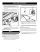
5. Using a wrench, raise or lower the front of deck by turning lock nut on the
front deck lift rod and secure with the rear jam nuts. See Figure 33.
Lock Nuts
Figure 33
6. The deck is properly leveled when the front tip of the blade is ⁄” lower than the
rear tip. Retighten the hex bolt on the left rear deck hanger links when proper
adjustment is achieved.
Adjusting the Front Gauge Wheels
WARNING
Keep hands and feet away from the discharge opening of the cutting deck.
The front gauge wheels on the mower deck are an anti-scalp feature, and should
not ride on the ground. The front gauge wheels should be approximately ⁄⁄”
above the ground when the deck is set in the desired height setting.
Using the deck lift handle, set the deck in the desired height setting, then check the
gauge wheel distance from the ground below. If necessary adjust the front gauge
wheels as follows:
1. Visually check the distance between the front gauge wheels and the ground.
If the gauge wheels are near or touching the ground, they should be raised. If
more than ⁄” above the ground, they should be lowered.
2. Remove the lock nut securing one of the front gauge wheel hex screws to the
deck. Remove the gauge wheel, hex screw and spacer. See Figure 34.
Lock Nut
Wheel
Hex Screw
Spacer
Figure 34
3. Insert the hex screw into the one of three index holes in the front gauge
wheel bracket that will give the gauge wheel a ⁄⁄” clearance with the
ground.
4. Note the index hole of the just adjusted wheel, and adjust the other front
gauge wheel into the respective index hole of the other front gauge wheel
bracket.
Drive Control Lever Stop Adjustment
When the drive control levers are both fully extended forward to the full-speed
position and the tractor drifts left or right, the drive control lever stop adjustment
can be adjusted to sync the wheel speeds. To perform the adjustment, proceed as
follows:
1. Identify the side that the tractor is drifting to and adjust the opposite drive
control lever. If the tractor drifts right, adjust the left control lever down
(decrease speed) and vice versa.