
Owners manual

9
ASSEMBLY
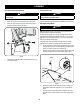
Lower Deck Discharge Chute Deflector
WARNING
Never operate the mower deck without the chute deflector installed and in
the down position.
The discharge chute deflector must be installed before operating the mower.
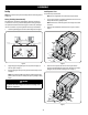
1. Remove the keys that are attached with a zip tie to the chute bracket.
2. Remove the carriage screws, flange lock nuts and flat washers from the
hardware pack in your manual bag. See Figure 6.
Figure 6
3. With the previously removed hardware, install the chute deflector on the
deck as shown in Figure 6.
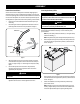
Checking Tire Pressure
WARNING
Do not overinflate tires. Check sidewall of tires for maximum psi. Equal tire
pressure should be maintained at all times.
The tires on your riding mower may be over inflated for shipping purposes. Reduce the
tire pressure before operating the riding mower. Check sidewall of tires for maximum psi.
Adjusting the Gauge Wheels
WARNING
Keep hands and feet away from the discharge opening of the cutting deck.
NOTE: The deck gauge wheels are an anti-scalp feature of the deck and are not
designed to support the weight of the cutting deck.
The mower deck cutting height can be set in any of six height settings using the
riding mower’s deck lift handle. The deck heights range from 1-⁄” to 4”. The deck
gauge wheel position should be approximately ⁄” to ⁄” above the ground when
the deck is set in the desired height setting.
Using the lift handle, set the deck in the desired height setting, then check the
gauge wheel distance from the ground below. If necessary adjust as follows:
1. Visually check the distance between the front gauge wheels and the ground.
If the gauge wheels are near or touching the ground, they should be raised. If
more than ⁄” above the ground, they should be lowered.
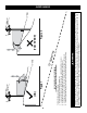
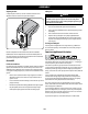
2. Remove the lock nut securing one of the front gauge wheel hex screws to the
deck. Remove the gauge wheel, hex screw and spacer. Refer to Figure 7.
Lock Nut
Wheel
Hex Screw
Spacer
Figure 7
3. Insert the hex screw into the one of three index holes in the front gauge
wheel bracket that will give the gauge wheel a ⁄-⁄” clearance with the
ground.
4. Note the index hole of the just adjusted wheel, and adjust the other front
gauge wheel into the respective index hole of the other front gauge wheel
bracket.