Owner's Manual/Manual Del Propietario 1/2 HP 315_N= GARAGE DOOR OPENER ABRIDOR DE PUERTA DE COCHERA For Residential 315_.= Use Only Model • 139.53930D m Z t.n rrl t.n z_ o Read and follow all safety rules and operating instructions before first use of this product. Leer y seguir todas las reglas de seguridad y las instrucciones de operacion antes de usar este producto por primera vez. Fasten the manual near the garage door after installation.
TABLE OF CONTENTS Introduction 2- 7 Safety symbol and signal word review ............. Preparing your garage door ...................... Tools needed ................................. Planning ................................... Carton inventory Adjust the travel limits ......................... 27 3 3 Adjust the force .............................. 28 Test the safety reversal system .................. 29 Test The Protector System ® ..................... 29 6 ............................
Preparing your garage door Before you begin: • Disable locks. To prevent possible SERIOUSINJURYor DEATH: • ALWAYScall a trained door systems technician if garage door binds, sticks, or is out of balance An unbalanced garage door may not reverse when required • NEVERtry to loosen, move or adjust garage door, door springs, cables, pulleys, brackets or their hardware, all of which are under EXTREMEtension • Remove any ropes connected to garage door.
Planning Identify the type and height of your garage door. Survey your garage area to see if any of the conditions below apply to your installation. Additional materials may be required. You may find it helpful to refer back to this page and the accompanying illustrations as you proceed with the installation of your opener. Depending on your requirements there are several installation steps which may call for materials or hardware not included in the carton.
Planning (Continued) ONE-PIECE DOOR INSTALLATIONS • Generally, a one-piece door does not require reinforcement. If your door is lightweight, refer to the information relating to sectional doors in Installation Step 11. • Depending on your door's construction, you may need additional mounting hardware for the door bracket (Step 11). Without a properly working safety reversal system, persons (particularly small children) could be SERIOUSLYINJUREDor KILLED by a closing garage door.
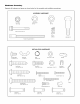
Carton Inventory Your garage door opener is packaged in one carton which contains the motor unit and all parts illustrated below. Accessories will depend on the model purchased. If anything is missing, carefully check the packing material. Parts may be stuck in the foam. Hardware for assembly and installation is shown on the next page. Save the carton and packing material until installation and adjustment is complete.
Hardware Inventory Separate all hardware and group as shown below for the assembly and installation procedures.
ASSEMBLY Assemble STEP 1 the Rail & Install the Trolley To avoid installation difficulties, do not run the garage door opener until instructed to do so. To prevent INJURYfrom pinching, keep hands and fingers away from the joints while assembling the rail. The front rail has a cut out "window" at the door end (see illustration). The hole above this window is larger on the top of the rail than on the bottom. A smaller hole 3-1/2" (8.9 cm) away is close to the rail edge.
ASSEMBLY Fasten the STEP Rail 2 to the Motor Unit To avoid SERIOUSdamageto garage door opener, use ONLY those bolts/fasteners mounted in the top of the opener. • Insert a 1/4"-20xl-3/4 bolt into the cover protection bolt hole on the back end of the rail as shown. Tighten securely with a 1/4"-20 lock nut. Do NOTovertighten. • Remove the two bolts from the top of the motor unit. • Place the "U" bracket, flat side down onto the motor unit and align the bracket hole with the bolt holes.
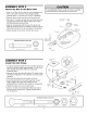
ASSEMBLY Install the STEP 4 Chain/Cable To avoid possible SERIOUSINJURYto fingers from moving garage door opener: • ALWAYSkeep hand clear of sprocket while operating opener. • Securely attach chain spreader BEFOREoperating. 1. Pull the cable around the idler pulley and toward the trolley. 2. Connect the cable to the retaining slot on the trolley, as shown (Figure 1): • From below, push pins of master link bar up through cable link and trolley slot.
ASSEMBLY Tighten the STEP 5 Chain Figure 1 • Spin the inner nut and lock washer down the trolley threaded shaft, away from the trolley. Outer Lock Nut Washer Trolley Threaded Shaft • To tighten the chain, turn outer nut in the direction shown (Figure 1). • When the chain is approximately 1/4" (6 mm) above the base of the rail at its midpoint, re-tighten the inner nut to secure the adjustment. Sprocket noise can result if chain is too loose.
INSTALLATION Determine Location the STEP Header 1 Unfinished Oei,og 7---jr Bracket _ J _ \ OPT O.AL __\CEtUNG J4 MOUNT _ FOR ._ yj HEADER _ BRACKET Vertical Centerline of Garage Door To prevent possible SERIOUSINJURYor DEATH: • Header bracket MUST be RIGIDLYfastened to structural support on header wall or ceiling, otherwise garage door might not reverse when required. DO NOTinstall header bracket over drywall. • Concreteanchors MUST be used if mounting header bracket or 2x4 into masonry.
INSTALLATION Install the Header STEP 2 Wall Mount Bracket You can attach the header bracket either to the wall above the garage door, or to the ceiling. Follow the instructions which will work best for your particular requirements. Do not install the header bracket over drywall. If installing into masonry, use concrete anchors (not provided).
INSTALLATION Attach the STEP Rail to the 3 Header Bracket NOTE: (Optional) With some existing installations, you may re-use the old header bracket with the two plastic spacers included in the hardware bag. Place the spacers inside the bracket on each side of the rail, as illustrated. • Position the opener on the garage floor below the header bracket. Use packing material as a protective base. NOTE: If the door spring is in the way you'll need help.
INSTALLATION Position the STEP 4 Opener To prevent damage to garage door, rest garage door opener rail on 2x4 placed on top section of door. Follow instructions which apply to your door type as illustrated. SECTIONAL TRACK DOOR OR ONE-PIECE DOOR WITH A 2x4 laid flat is convenient for setting an ideal door-to-rail distance. Rail • Remove foam packaging. i !. • Raise the opener onto a stepladder. You will need help at this point if the ladder is not tall enough.
INSTALLATION Hang the STEP 5 Opener To avoid possible SERIOUSINJURYfrom a falling garage door opener, fasten it SECURELYto structural supports of the garage. Concrete anchors MUST be used if installing any brackets into masonry. Three representative installations are shown. Yours may be different. Hanging brackets should be angled (Figure 1) to provide rigid support. On finished ceilings (Figure 2 and Figure 3), attach a sturdy metal bracket to structural supports before installing the opener.
INSTALLATION Install the Door STEP 6 Control To prevent possible SERIOUSINJURYor DEATHfrom electrocution: Locate door control within sight of door, at a minimum height of 5 feet (1.5 m) where small children cannot reach, away from moving parts of door and door hardware. If installing into drywall, drill 5/32" holes and use the anchors provided. For pre-wired installations (as in new home construction), it may be mounted to a single gang box (Figure 2).
INSTALLATION Install the STEP 7 Light To prevent possible OVERHEATING of the endpanel or light socket, • DO NOT use short neck or specialty light bulbs. • DO NOT use halogen bulbs. Use ONLYincandescent. To prevent damage to the opener: • DO NOT use bulbs larger than IOOW. • ONLYuse A19 size bulbs. • Press the release tabs on both sides of lens. Gently rotate lens back and downward until the lens hinge is in the fully open position. Do not remove the lens.
INSTALLATION Electrical STEP 9 Requirements To prevent possible SERIOUSINJURYor DEATHfrom electrocution or fire: To avoid installation difficulties, do not run the opener at this time. • Be sure power is not connected to the opener, and disconnect power to circuit BEFOREremoving cover to establish permanent wiring connection. • Garagedoor installation and wiring MUST be in compliance with all local electrical and building codes.
INSTALLATION Install The STEP Protector 10 System ® Be sure power is not connectedto the garage door opener BEFOREinstalling the safety reversing sensor. To prevent SERIOUSINJURYor DEATHfrom a closing garage door: • Correctly connect and align the safety reversing sensor. This required safety device MUST NOTbe disabled. • Install the safety reversing sensor so beam is NO HIGHER than 6" (15 cm) above garage floor.
INSTALLING THE BRACKETS Be sure power to the opener is disconnected. Install and align the brackets so the sensors will face each other across the garage door, with the beam no higher than 6" (15 cm) above the floor. They may be installed in one of three ways, as follows. Garage door track installation Figure 1 DOOR TRACK MOUNT (RIGHT SIDE) Door Track (preferred): Indicator Light • Slip the curved arms over the rounded edge of each door track, with the curved arms facing the door.
MOUNTING AND WIRING THE SAFETY REVERSING SENSORS Figure 5 Wing Nut 1/4"-20 • Slide a 1/4"-20xl/2" carriage bolt head into the slot on each sensor. Use wing nuts to fasten sensors to brackets, with lenses pointing toward each other across the door. Be sure the lens is not obstructed by a bracket extension (Figure 5). Carriage Bolt 1/4"-20xl/2" --_ "Lens • Finger tighten the wing nuts. • Run the wires from both sensors to the opener. Use insulated staples to secure wire to wall and ceiling.
INSTALLATION Fasten the Door STEP 11 Bracket Fiberglass, aluminum or lightweight steel garage doors WILL REQUIREreinforcement BEFOREinstallation of door bracket. Contact your door manufacturer for reinforcement kit. Follow instructions which apply to your door type as illustrated below or on the following page. A horizontal reinforcement brace should be long enough to be secured to two vertical supports. A vertical reinforcement brace should cover the height of the top panel.
ONE-PIECE DOORS Please read and comply with the warnings and reinforcement instructions on the previous page. They apply to one-piece doors also. • Center the door bracket on the top of the door, in line with the header bracket as shown. Mark either the left and right, or the top and bottom holes. • Drill 5/16" pilot holes and fasten the bracket with hardware supplied.
INSTALLATION Connect Door STEP Arm 12 to Trolley Follow instructions which apply to your door type as illustrated below and on the following page. SECTIONAL DOORS ONLY • Make sure garage door is fully closed. Pull the emergency release handle to disconnect the outer trolley from the inner trolley. Slide the outer trolley back (away from the pulley) about 8" (20 cm) as shown in Figures 1, 2 and 3. • Figure 1: - Fasten straight door arm section to outer trolley with the 5/16"x1" clevis pin.
ALL ONE-PIECE DOORS 1.Assemble Door Bracket the door arm, Figure 4: Fastener Clevis Pin 5/16"x1-1/4" • With the door closed, connect the straight door arm section to the door bracket with the 5/16"x1-1/4" clevis pin. procedures, - Press the Door Control push button. The trolley will travel to the fully closed position. • On one-piece doors, before connecting the door arm to the trolley, the travel limits must be adjusted. Limit adjustment screws are located on the left side panel as shown on page 27.
ADJUSTMENT Adjust the STEP UP and DOWN 1 Travel Limits Without a properly installed safety reversal system, persons (particularly small children) could be SERIOUSLYINJUREDor KILLED by a closing garage door. • Incorrect adjustment of garage door travel limits will interfere with proper operation of safety reversal system. • If one control (force or travel limits) is adjusted, the other control may also need adjustment. • After ANY adjustments are made, the safety reversal system MUST be tested.
ADJUSTMENT Adjust the STEP 2 Force Without a properly installed safety reversal system, persons (particularly small children) could be SERIOUSLYINJUREDor KILLED by a closing garage door. • Too much force on garage door will interfere with proper operation of safety reversal system. • NEVERincrease force beyond minimum amount required to close garage door. • NEVERuse force adjustments to compensate for a binding or sticking garage door.
ADJUSTMENT Test the Safety STEP 3 Reversal System Without a properly installed safety reversal system, persons (particularly small children) could be SERIOUSLYINJUREDor KILLED by a closing garage door. • Safety reversal system MUST be tested every month. • If one control (force or travel limits) is adjusted, the other control may also need adjustment. • After ANY adjustments are made, the safety reversal system MUST be tested. Door MUST reverse on contact with 1-1/2" high (3.
OPERATION IMPORTANT SAFETY INSTRUCTIONS To reduce the risk of SEVERE INJURY or DEATH: 1. READAND FOLLOWALL WARNINGSAND INSTRUCTIONS. 2. ALWAYSkeep remote controls out of reach of children. NEVERpermit children to operate or play with garage door control push buttons or remote controls. 3. ONLYactivate garage door when it can be seen clearly, it is properly adjusted, and there are no obstructions to door travel. 4. ALWAYSkeep garage door in sight until completely closed.
Using the Wall.Mounted Door Press the lighted push button to open or close the door. Press again to reverse the door during the closing cycle or to stop the door while it's opening. To Open Control I the Door Manually To prevent possible SERIOUSINJURYor DEATHfrom a failing garage door: • If possible, use emergency releasehandle to disengage trolley ONLYwhen garage door is CLOSED.Weak or broken springs or unbalanced door could result in an open door falling rapidly and/or unexpectedly.
CARE OF YOUR OPENER GARAGE LIMIT AND FORCE ADJUSTMENTS: Weather conditions may cause some minor changes in door operation requiring some readjustments, particularly during the first year of operation THE REMOTE CONTROL BATTERY DOOR FORCE CONTROLS To prevent possible SERIOUSINJURYor DEATH: • NEVERallow small children near batteries • If battery is swallowed, immediately notify doctor The lithium battery should produce power for up to LIMITCONTROLS openthisend first to avoidJ _....
HAVING A PROBLEM? 1. My door will not close and the light bulbs blink on my motor unit: The safety reversing sensor must be connected and aligned correctly before the garage door opener will move in the down direction. Bell Wire • Verify the safety sensors are properly installed, aligned and free of any obstructions. Refer to Installation Step 10: Install The Protector Syster_. • Check diagnostic LED for flashes on the motor unit then refer to the Diagnostic Chart on the following page. 2.
Bell Wire \ Installed Safety Reversing Sensor Diagnostic Your garage door opener is programmed with self-diagnostic capabilities. The "Learn" button/diagnostic LED will flash a number of times then pause signifying it has found a potential issue. Consult Diagnostic Chart below. Chart Safety reversing sensors wire open (broken or disconnected). OR Symptom: One or both of the Indicator lights on the safety sensors do not glow steady.
PROGRAMMING NOTICE: If this Security.l_ garage door opener is operated with a non-rolling code transmitter, the technical measure in the receiver of the garage door opener, which provides security against code-theft devices, will be circumvented. The owner of the copyright in the garage door opener does not authorize the purchaser or supplier of the non-rolling code transmitter to circumvent that technical measure.
To Add, Reprogram or NOTE: Your new Keyless Entry must be programmed USING THE "LEARN" Change a Keyless Entry PIN to operate your garage door opener, BUTTON To set a temporary PIN You may authorize access by visitors or service people with a temporary 4-digit PIN. After a programmed number of hours or number of accesses, this temporary PIN expires and will no longer open the door. It can be used to close the door even after it has expired. To set a temporary PIN: ) 1.
REPAIR Rail PARTS Assembly Parts 3 6 KEY NO. PART NO. DESCRIPTION 1 4A1008 Master link kit 2 41C5141-1 Complete trolley assembly 3 41A5665-2 Complete rail 4 5 144C56 41A5807 Idler pulley Chain and cable 6 12D598-1 "U" bracket NOT SHOWN 183A163 Installation Wear pads Parts \\ KEY NO. PART NO.
Motor Unit Assembly 7 Parts \ \ 19 8 / 17 15 Brown (Down) Contact Contact KEY NO. PART NO. LIMIT SWITCH ASSEMBLY Contact 11 Wire 12 DESCRIPTION KEY NO. PART NO.
ACCESSORIES 139.53702 139.53753 Emergency Key Release: Required for a garage with NO access door. Enables homeowner to open garage door manually from outside by disengaging trolley. 139.53726 139.53752 To allow an 8 (2.4 m) foot door to open fully. Security+ ®Keyless Entry: Enables homeowner to operate garage door opener from outside by entering a 4 digit code on specially designed keypad. 139.