Owner’s Manual CRHFTSMBN* 1/2 HP GARAGE DOOR OPENER For Residential Use Only Model No: 139.53978SRT CAUTION: Read and follow all safety rules and operating instructions before first use of this product. Fasten the manual near the garage door after installation. Complies with UL 325 regulations effective January 1, 1993 Sears, Roebuck and Co., Hoffman Estates, IL 60179 U.S.A Visit our Craftsman website: www.sears.
Contents Page Contents Page A review of safety alert symbols..................... 2 Install the light and lens................................................. 19 You'll need toots.............................................3 Attach emergency release rope and handle................. 19 Safety information regarding garage door locks Electrical requirememts................................................. 20 and ropes......................................................
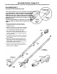
You'll Need Tools During assembly, installation and adjustment of the opener, instructions will call for hand tools shown below. Hack Saw Claw Hammer Screwdriver Locking pliers An unbalanced garage door might not reverse when required and someone under the door couid be seriously injured or killed, if your garage door binds, sticks or is out of balance, call for professional garage door service.
Before you begin, survey your garage area to see whether any of the conditions beiow appiy to your installation. ' FINISHED CEILING Support bracket & fastening hardware is required. Seepage 17. Horizontal and vertical reintotcement is needed for lightweight garage doors (fiberglass, steel, aluminum, door with glass panels, etc.). See page 24 for details.
One-Piece Door without Track Before you begin, survey your garage area to see whether any of the conditions beiow apply to your installation. Reversing between floor and bottom Sensor Safety of door must not exceed 1/4'. Reversing Sensor FINISHED C0LING Support bracket & fastening hardware is teguired. See page 17. One-Piece Door with Track Based on your particular requirements, there are severai instaiiation steps which might call for materials and/or hardware not included in the carton.
Carton Inventory Your garage door opener is packaged in two cartons which contain parts illustrated below. Accessories will depend on model purchased. If anything is missing, carefully check the packing material. Parts may be "stuck“ in the foam. Hardware for assembly and installation is shown on page 7.
Separate all hardware from the packages in the rail carton and the opener carton, as shown below, for the assembly and installation procedures.
Assembly Section: Pages 8-11 To avoid installation difficulties, do not run the garage door opener until instructed to do so. Assembly Step 1 Assemble the Rail & Install the Trolley The front rail has a cut out “window" at the door end (see illustration). The hole above this window is larger on the top of the rail than on the bottom . A sm aller hole 3-1/2“ away is dose to the rail edge. The back rail has a sim ilar hoie dose to the edge, about 4-3/4“ from the far end. A 3-piece rail uses two back rails.
Assembly Step 2 Fasten the Rail to the Opener To fasten rail, use only those screws mounted in the top of the opener. Any other screws will cause serious damage to the opener. Insert a 1/4"-20x1 -3/4 bolt into the cover protection bolt hole on the back end of the rail as shown. Tighten securely with a 1/4"-20 lock nut. Remove the two screws from the top of the opener. Place the U bracket, fiat side down, on the opener and align the bracket holes with the screw holes.
Assembly Step 4 Install the Chain/Cable and Attach the Sprocket Cover Serious injury can result if fingers become entangled in moving opener sprocket. Attach sprocket cover securely. Never operate opener while your hand is near the opener sprocket. 1. Pull the cable around the idler pulley and toward the trolley. 2. Connect the cable loop to the retaining slot on the trolley, as shown: • From below, push pins of master link bar up through cable loop and trolley slot.
Assembly Step 5 Tighten hie Chain • Spin the inner nut and lock washer down the Figure 1 threaded shaft, away from the trolley. Outer Lock Nut Washer • To tighten the chain, turn outer nut in the direction shown (Figure 1). Trolley shaft • When the chain is approximately 1/2" above the base of the rail at its midpoint, re-tighten the inner nut to secure the adjustment. Sprocket noise can result if chain is too loose.
Installation Section: Pages 12-27 Installation Step 1 Determine Header Bracket Location It the header bracket is not rigidly fastened to a structural support on the header wall or ceiling, the safety reverse system may not work properly (see page 30). The door might Installation procedures vary according to garage door types. Follow the instructions which appiy to your door. not reverse when required, and serious injury or death.
Read the Safety Instructions on page 12. They also apply to doors without tracks. • Close the door and mark the inside vertical centerline of your garage door. Extend the line onto the header wall above door. If headroom clearance is minimal, you can install the header bracket on the ceiling. See page 14.
You can attach the header bracket either to the wall above the garage door, or to the celling. Follow the instructions which will work best for your particular requirements. Installation Step 2 InstaU the Header Bracket Wall Header Bracket Installation Center the bracket on the vertical guideline with the bottom edge of the bracket on the horizontal line as shown (with the arrow pointing toward the ceiling). • Mark the vertical set of bracket holes.
Installation Step 3 Attach the Rail to the Header Bracket NOTE: (Optional) W ith an existing Craftsm an installation, you m ay re-use the old header brack with the two plastic spacers included in the hard bag. Place the spacers inside the bracket on eac side of the rail, as illustrated. • Position the opener on the garage floor below the header bracket. Use packing materia! as a protective base. if the door spring is in the way you'li need help.
Installation Step 4 Position the Opener Follow instructions which apply to your door type as illustrated. To prevent damage to steel, aluminum, fiberglass or glass panel doors, do not rest the opener on the door without using a 2x4. A 2x4 laid flat is convenient for setting an ideal door-to-T-rail distance. • Raise the opener onto a stepladder as shown. You will need help at this point if the ladder is not tall enough.
Installation Step 5 Hang the Opener The opener could fall and Injure someone if it is not properly secured. Fasten the opener securely to structural supports of the garage. Two representative installations are shown. Yours may be different. Hanging brackets should be angled, Figure 1, to provide rigid support. On finished ceilings, Figure 2, attach a sturdy metal bracket to structural supports before installing the opener. The bracket and fastening hardware are not provided. See accessory page 38.
Installation Step 6 Instan the Door Control Do not connect to five etectricat mnng. Connect only to 24 Volt low voltage wires. Connection to Locate the door control within sight of the door atorahigher voltage may cause serious live wires m inim um height of 5 feet where sm all children injury from shock, bum or electrocution. cannot reach, and away from all m oving parts of the Children operating or playing with a garage door and door hardware. door opener can injure themselves or others.
6. Attach the User Safety Instruction label to the wall near the door control, and frie Maintenance Instruction label in a prominent location on the inside of the garage door. Do NOT connect the power and operate the opener at this time. The trolley will travel to the full open position but will not return to the dose position until the sensor beam is connected and properly aligned. See Safety Reversing Sensor instructions beginning on page 21. Page 32 explains how to use the door control.
Installation Step 9 Electrical Requirements To prevent electrocution or fire, installation and wiring must be in compliance with local electrical and building codes. Do NOT use an extension cord, 2-wire adapter, or change the plug in any way to make it fit your outlet. To reduce the risk of electric shock, your garage door opener has a grounding type plug with a third grounding pin. This plug will onlyiW into a grounding type outlet.
The Safety Reversing System IMPORTANT INFORMATION ABOUT THE SAFETY REVERSING SENSOR The safety reversing sensor must\i& connected and aligned correctly before the garage door opener will move in the down direction. This is a required safety device and cannot be disabled. Without a proparly working safety reversing sensor, persons (particuiariy chiidren) could be injur^ or killed by a dosing garage door. Read and follow all instructions.
Figure 2 door track mount (Right side) INSTALLING THE BRACKETS Be sure power to the opener is disconnected. Install and align the brackets so the sensors will face each other across the garage door, with the beam from 4 - 6“ above the floor. They may be installed in one of three ways, as follows. Garage door track installation (preferred): • Slip the curved arms over the rounded edge of Figure 3 wall mount (Right side) each door track, with the curved arms facing the door.
MOUNTING AND WIRING THE SAFETY SENSORS Figure 5 • Slide a 1/4"-20x1/2" carriage bolt head into the slot on each sensor. Use wing nuts to fasten sensors to brackets, with lenses pointing toward each other across the door. Be sure the lens is not obstructed by a bracket extension. See Figure 5. • Finger tighten the wing nuts. • Run the wires from both sensors to the opener. Use insulated staples to secure wire to wail and ceiling. • Strip 1/4" of insulation from each set of wires.
Installation Step 11 Fasten Door Bracket To prevent damage to steel, aluminum, fibergiass or giass panei doors, always reinforce the inside of the door both verticaily and horizontaily with an angle Iron. Follow instructions which apply to your door type as illustrated below or on page 25. A horizontal brace should be long enough to be secured to 2 vertical supports. A vertical brace should cover the height of the top panel. The illustration shows one piece of angle iron as the horizontal brace.
Please read and comply with the warnings and reinforcement instructions on page 24. They apply to one-piece doors aiso. Header Wall • Center the bracket on the top of the door, in line with the header bracket as shown. Mark holes. • Drill 5/16" pilot holes and fasten the door bracket with hardware provided. If the door has no exposed framing, drill 3/16" pilot holes and fasten the bracket with 5/16"x1-1/2" lag screws (not provided) to the top of the door.
Installation Step 12 Connect Door Arm to Trolley Follow instructions which apply to your door type as illustrated below and on page 27. ....... .................................................................... Make sure garage door is fully closed. Puil the emergency release handle to disconnect the outer trolley from the inner trolley. Slide the outer trolley back (away from the pulley) for 8" minimum as shown below.
Assemble the Door Arm: Ring -------- Fastener • Fasten the straight and curved door arm sections together to the longest possible length {with a 2 or 3 hole overiap). Nuts • With the door closed, connect the straight door ann section to the door bracket with the 5/16"x1 -1/4" clevis pin. Screws 5/16'-18x7/8 • Secure with a ring fastener. On one-piece doors, before connecting the door arm to the trolley the travel limits must be adjusted.
Adjustment Section: Pages 28 - 30 Adjustment Step 1 Adjust the UP and DOWN Limits Improper adjustment of the travel limits will interfere with the proper operation of the safety reverse system. The door might not reverse Do not make any limit adjustments until the safety reversing sensors are completely installed. properly when required and could seriously injure or km someone under It. Test the safety Limit adjustment settings regulate the points at which the door will stop when moving up or down.
Adjustment Step 2 Adjust the Force Too much force on the door will interfere with the proper operation of the safety reverse system. The door might not reverse property Force adjustment controls are located on the back panel of the opener. Force adjustment settings regulate the amount of power required to open and close the door. when required and could seriously injure or kill someone under it. Do not increase the force beyond the minimum amount required to ciose the door.
Adjustment Step 3 Test The Safety Reversing Sensor W ithout a properly working safety reversing sensor, persons (particularly children) could be seriously injured or killed if trapped by a dosing garage door. Repeat this test once a • Press the remote control push button to open the door. month. • Place the opener carton in the path of the door. • Press the remote control push button to close the door. The door will not m ove m ore than an inch, and the opener light will flash.
IMPORTANT SAFETY INSTRUCTIONS To reduce the risk of severe injury or death to persons: 1. READ AND FOLLOW ALL INSTRUCTIONS. 2. Do not permit children either to operate or to play with the opener. Keep remote control in a location inaccessible to children. 3. Operate opener only when the door is in full view and free from any obstruction. Keep the door in sight until it is completely closed. NO ONE SHOULD CROSS THE PATH OF THE MOVING DOOR. 4. Check safety reversal system monthly. See page 30.
Operation of Your Opener Activate the opener with any of the following: • The Remote Control: Hold push button down until the door starts to move. • The Door Control; Hold push button down until Weak or door to resulting damage. the door starts to move. • The Outdoor Key Switch or Keyless Entry. broken springs could allow an open fall (either rapidly or unexpectedly), in serious injury, death or property If possible, use the emergency release rope and handle o/7//when the door is fully closed.
Receiver and Remote Control Programming To comply with FCC rules, adjustment or modifications o( this receiver and/or SECUliri'Y^' transmitter are prohibited, except for changing the code setting or replacing the battery. THERE ARE NO OTHER USER SERVICEABLE PARTS. Your garage door opener receiver and remote control have been pre-set at the factory. The door will open when you press the LARGE remote control push button.
Having a Problem? Situation Probable Cause and Solution The opener doesn t operate from either the Door Controlar the remote control: 1. Does the opener have electric power? Plug a lamp into the outlet. If it doesn’t light, check the fuse box or the circuit breaker. (Some outlets are controlled by a wall switch.) 2. Have you disabled all door locks? Review installation ihstruction warnings on Page 11. 3. Is there a build-up of ice or snow under the door? The door may be frozen to the ground.
Having a Problem? (continued) Situation The door opens but won't dose: Probable Cause & Solution 1. If the opener lights blink, check the safety reversing sensor. See page 23. 2. If the opener lights do not blink and it is a new installation, check thè down force. See Adjustment Step 2, page 29. For an existing installation, see below. Repeat the safety reverse test after the adjustment is compiete. The door reverses for no apparent reason and opener lights don't blink: 1.
Repair Parts Rail Assembly Parts KEY NO. 1 2 1A995 41C5141-1 3 4 5 183C158-3 6 7 8 Installation Parts KEY PART NO. NO. 1 2 3 41A4899 10A20 41A5032 4 5 6 7 8 9 10 11 12 13 14 15 29B137 41A2828 217A238 12B590 41A5047 178B35 31D431 10A2 31B430 178B34 12B350 41A5034 16 2B477-1 41A5258 114A2400 DESCRIPTION Standard control console 3V 2032 Lithium battery 3-function remote control housing (no circuit board) Visor clip Emergency rope & handle assy.
Repair Parts Opener Assembly Parts Drive Gear Center Limit Contact KEY PART NO. NO. 1 2 31D380 41C4220A 41A2817 4 5 6 7 8 9 10 41B4245 41A4352 175B88 108D58-2 30B363 12A373 41A31S0 (Up) Contact KEY PART NO. NO.
Accessories Sears offers many useful accessories for your garage door opener. They are illustrated below with Sears model numbers and descriptions. 139.53702 Emergency Key Release: 139.53681 Required\ox a garage with NO access door. Enables homeowner to open garage door manually from outside by disengaging trolley. 139.53703 Includes visor clip. Outdoor Key Switch: 139.53680 Operates the garage door automatically from outside when remote control is not handy. 53724 8 Foot Rail Extension 139.
Index Access Door/Outside Key Release Accessory...................................................................................................................4.5 Chain Tension................................................................................................................................................................. 4, 5,11 Electricai Safety Warnings.........................................................................................................................................
For in-home major brand repair service: Call 24 hours a day, 7 days a week 1-800-4-MY-HOME^“ (1 -800-469-4663) Para pedir servicio de reparación a domiciiio -1-800-676-5811 For the repair or repiacement parts you need: Call 6 a.m. - 11 p.m. CST, 7 days a week PartsDirecf“ 1 -800-366-PART (1 -800-366-7278) www.sears.