Operator’s Manual 10-in. DRILL PRESS 1/2 HP MOTOR Model 124.34983 CAUTION: Before using this product, read this manual and follow all its Safety Rules and Operating Instructions. Sears Brands Management Corporation, Hoffman Estates, IL 60179 U.S.
TABLE OF CONTENTS Warranty..........................................................................................................................................................................................2 Safety Instructions.....................................................................................................................................................................................2-3 Specifications................................................................................
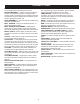
17. NEVER STAND ON TOOL. Serious injury could occur if the tool is tipped or if the cutting tool is unintentionally contacted. 18. CHECK FOR DAMAGED PARTS. Before further use of the tool, a guard or other part that is damaged should be carefully checked to determine that it will operate properly and perform its intended function – check for alignment of moving parts, binding of moving parts, breakage of parts, mounting, and any other conditions that may affect its operation.
GLOSSARY OF TERMS BASE – Supports drill press. For additional stability, holes are provided in base to bolt drill press to bench. BACKUP MATERIAL – A piece of scrap wood placed between the workpiece and table. The backup board prevents wood in the workpiece from splintering when the drill passes through the backside of the workpiece. It also prevents drilling into the table top. HEAD ASSEMBLY – Covers the pulleys and belt during operation of the drill press.
SAFETY ELECTRICAL REQUIREMENTS POWER SUPPLY AND MOTOR SPECIFICATIONS WARNING: To avoid electrical hazards, fire hazards, or damage to the tool, use proper circuit protection. Use a separate electrical circuit for your tools. To avoid shock or fire, if power cord is worn or cut, or damaged in any way, have it replaced immediately. GROUNDING INSTRUCTIONS WARNING: This tool must be grounded while in use to protect the operator from electrical shock.
ACCESSORIES AND ATTACHMENTS CARTON CONTENTS UNPACKING AND CHECKING CONTENTS Carefully unpack the Drill Press and all its parts, and compare against the illustration following. WARNING: • To avoid injury from unexpected starting, do not plug the power cord into a power source receptacle during unpacking and assembly. This cord must remain unplugged whenever you are assembling or adjusting the drill press.
CARTON CONTENTS B. Accessories (in one separate box) See Fig.2 A. Feed handles B. Crank handle C. Hex wrenches D. Hex bolts E. Chuck key F. Chuck G. Table fence set Table Fence Use the supplied hardware to attach the fence to the table as shown in the picture below. Use the fence to align the workpiece and provide a backstop for secure drilling.
ASSEMBLY 1. Column support to base 1.1 Position the base on floor or bench. 1.2 Place the column on the base, aligning the holes in the column support with the holes in the base. 1.3 Locate the four long hex bolts from the loose parts bag. 1.4 Place a bolt in each hole through the column support and the base. Tighten with an adjustable wrench. See Fig. 1 Figure 1 2. Installing the Table 2.1 Loosen set screw (1). Remove rack (2) and retaining ring (3) from column (4). Fig. 2A 2.
ASSEMBLY 3. Installing the head assembly 3.1. Carefully lift the head assembly above the column and slide it onto the column. Make sure the head slides down over the column as far as possible. Align the head with the base. 3.2. Using the hex wrench, tighten the head lock set screws. See Fig. 6 4. Installing feed handles 4.1. Locate the three feed handles in the loose parts box. 4.2. Screw the feed handles into the threaded holes in the hub. Tighten. Figure 6 See Fig. 7 5.
ADJUSTMENT WARNING: To prevent personal injury, always disconnect the plug from the power source when making any adjustment. 1. Table adjustment A. Height adjustment Loosen the clamp bolt then adjust the table to your desired position by turning the table bracket crank handle. See Fig. 10 Clamp bolt Crank handle B. Tilting adjustment: - On underside of table support bracket, back out set screw with supplied hex wrench. Loosen large hex head bolt. See Fig.
ADJUSTMENT 5. Spindle Spring Adjustment The spindle return spring may need adjustment if the tension causes the spindle to return too rapidly or too slowly. 5.1 Lower the table for additional clearance. 5.2 Place a screwdriver in the lower front notch (1) of the spring cap (2). Hold it in place while loosening and removing only the outer lock nut (3). 5.
OPERATION 1. Installing A Drill Bit See Fig. 17 1.1. With the switch “OFF”, open the chuck jaws (1) using the chuck key (2). Turn the chuck key counterclockwise to open the chuck jaws (1). 1.2. Insert the drill bit (3) into the chuck far enough to obtain maximum gripping by the jaws, but not far enough to touch the spiral grooves (flutes) of the drill bit when the jaws are tightened. 1.3. Make sure that the drill is centered in the chuck. 1.4. Turn the chuck key clockwise to tighten the jaws.
OPERATION Correct Drilling Speeds WARNING: Be sure drill press is turned off and is disconnected from power sours before adjusting speeds. Use the recommended speed for the drill bit and workpiece.
MAINTENANCE MAINTAINING YOUR DRILL PRESS LUBRICATION All of the drill press ball bearings are packed with grease at the factory. They require no further lubrication. Lower spindle to maximum depth and oil moderately once every three months. WARNING: For your own safety, turn the switch OFF and remove the plug from the power source outlet before maintaining or lubricating your drill press. Frequently blow out any dust that accumulates inside the motor with an air compressor or dust vacuum.
PARTS DIAGRAM 15
PARTS LIST KEY NO. 1 2 3 4-1 4-2 4-3 4-4 4-5 4-6 4-7 5 6 7 8 9 10 11 12 13 14 15 16 17 18 19 20 21 22 23 24 25 26 27 28 29 30 31 32 33 34 35 36 37 38 39 40 41 42 43 44 45 46 47 48 49 50 51 52 53 54 55B-1 55B-2 55B-3 55B-4 MFG. PART NO.
PARTS LIST (Cont.) KEY NO. 55B-5 55B-6 55B-7 55B-8 55B-9 55B-10 55B-11 55B-12 55B-13 55B-14 55B-15 55B-16 55B-17 55B-18 55B-19 55B-20 55B-21 55B-22 55B-23 55B-24 55B-25 55B-26 55B-27 56 57 58 59 60 61 62 63 64 65 66 67 68 69 70 71 72 73 74 75 76 77-1 77-2 77-3 78 79 80 81 82 83 MFG. PART NO.
REPAIR PROTECTION AGREEMENT Repair Protection Agreements Congratulations on making a smart purchase. Your new Craftsman® product is designed and manufactured for years of dependable operation. But like all products, it may require repair from time to time. That’s when having a Repair Protection Agreement can save you money and aggravation.
LISTA DE CONTENIDO Garantía..........................................................................................................................................................................................18 Las instrucciones de seguridad...................................................................................................................................18-19 Especificacións..................................................................................................................
17. Nunca se pare SOBRE LA HERRAMIENTA. Lesiones graves pueden ocurrir si la herramienta se inclina o si la herramienta de corte involuntariamente contactados. 18. DISPONER DE PARTES dañadas.
GLOSARIO DE TÉRMINOS GUÍAS BASE – Apoya drill press. Para obtener más VELOCIDAD DE PERFORACIÓN – Cambiarse situ- estabilidad, tiene cuatro orificios en la base para perno perforación presione al tribunal. MATERIAL DE COPIA DE SEGURIDAD – Un pedazo de madera de desecho colocado entre la pieza y el cuadro. La copia de seguridad impide junta madera en la pieza de astillamiento cuando el taladro pasa a través de la parte trasera de la pieza de trabajo.
SEGURIDAD NECESIDADES DE ENERGÍA ELÉCTRICA FUENTE DE ALIMENTACIÓN Y ESPECIFICACIONES DEL MOTOR ADVERTENCIA: Con el fin de evitar riesgos eléctricos, de incendio, o daños a la herramienta, utilice una adecuada protección contra cortocircuitos. Utilizar un circuito eléctrico separado para sus herramientas. La taladradora está inmovilizada en la fábrica de 115V. Conectar a 115V, circuito de 15 amperes y utilizar un retardo de 15 amperes fusibles ou.
ACCESORIOS Y COMPLEMENTOS EL CARTÓN CONTENIDO DESEMBALAJE Y COMPROBACIÓN CONTENIDO Desembálelo cuidadosamente la Taladradora y todas sus piezas, y comparar contra la ilustración siguiente. ADVERTENCIA: • Para evitar daños en caso de partida inesperada, no conecte el cable de alimentación a una fuente de alimentación recipiente durante desembalaje y el montaje. Este cable debe seguir siendo desconectado cuando se están reuniendo o ajustar la taladradora.
EL CARTÓN CONTENIDO B. Accesorios (en un recuadro aparte) See Fig.2 A. Piensos manejar B. Manivela C. Una llave hexagonal D. Tornillo Hexagonal E. Chuck clave F. Chuck G. Tabla valla Tabla Valla Usar el hardware para adjuntar la valla para la tabla como se muestra en la imagen de abajo. Utilice la valla para alinear la pieza de trabajo y proporcionar un apoyo seguro de perforación.
ASAMBLEA 1. La columna apoyo a base 1.1 Posición la base en el piso o banqueta. 1.2 Colocar la columna de la base, alineando los orificios en la columna soporte con los orificios en la base. 1.3 Busque los cuatro pernos hexagonal largo piezas sueltas de la bolsa. 1.4 Colocar el tornillo en cada agujero a través de la columna soporte y en la base. Apriete con una llave ajustable. See Fig. 1 Figura 1 2. Instalar la mesa 2.1 Afloje tornillo de ajuste (1).
ASAMBLEA 5. Instalar el jefe montaje 5.1. Levante con cuidado la cabeza asamblea por encima de la columna y deslícelo hacia la columna. Asegúrese de que la cabeza se desliza hacia abajo en la columna en la medida de lo posible. Alinee la cabeza con la base. 5.2. Utilizando la llave hexagonal, apriete la cabeza bloquear tornillos de ajuste. Primavera Pac See Fig. 6 6. Instalando alimentar maneja Figura 6 6.1. Busque los tres piensos controla en el cuadro de piezas sueltas. 6.2.
AJUSTE 1. Ajuste Tabla A. Ajuste de la Altura Para ajustar hacia arriba o hacia abajo. Afloje el tornillo de pinza luego ajustar la tabla a su posición deseada girando el cuadro bracket manivela. See Fig. 10 B. Inclinación: - En la parte inferior del cuadro escuadra de soporte, de vuelta de tornillo suministrados con una llave hexagonal. Afloje gran tornillo de cabeza hexagonal. - Gire tabla a ángulo deseado derecha o la izquierda. Utilice escala de bisel de ajuste preciso. See Fig.
AJUSTE 5. Fusiformes Ajuste Resorte El eje volver primavera puede necesitar un ajuste si la tensión causa al eje para volver demasiado rápido o demasiado lento. 5.1 Baje la mesa de espacio libre adicional. 5.2 Coloque un destornillador en la parte inferior delantera de primera (1) de la primavera (2). Manténgalo en el lugar mientras que aflojando y extraer sólo el exterior Figura 15B Figura tuerca (3). 5.
OPERACIÓN 1. Instalando una broca See Fig. 17 1.1. Con el interruptor “OFF”, abrir el chuck mandíbulas (1) usando el chuck clave (2). Gire el chuck clave las agujas del reloj para abrir el chuck mandíbulas (1). 1.2. Inserte la broca (3) en el chuck lo suficiente para obtener el máximo agarre de las mandíbulas, pero no lo suficiente para tocar el espiral surcos (flautas), de la broca cuando las mandíbulas se estrechan. 1.3. Asegúrese de que el taladro está centrada en la broca. 1.4.
OPERACIÓN 4. Corregir la perforación velocidades ADVERTENCIA: asegúrese de prensa perforadora está apagada y está desconectada sours antes de ajustar las velocidades. Utilizar la velocidad recomendada para la broca y pieza.
MANTENIMIENTO MANTENER LA TALADRADORA LA LUBRICACIÓN. Toda la prensa perforadora rodamientos de bolas están llenos de grasa en la fábrica. No es necesario dar mayores la lubricación. Eje inferior a profundidad máxima y moderadamente aceite una vez cada tres meses. ADVERTENCIA: Por su propia seguridad, apague el interruptor y quitar el conector de la fuente de energía antes del mantenimiento o lubricación de la taladradora.
REPARAR ACUERDO DE PROTECCIÓN REPARAR ACUERDO DE PROTECCIÓN Felicitaciones por hacer una compra inteligente. Su nuevo producto Craftsman® está diseñado y fabricado por años de funcionamiento confiable. Pero al igual que todos los productos, podrá exigir reparación de vez en cuando. Es entonces cuando habiendo una reparación acuerdo de protección le puede ahorrar dinero y a la agravación. Esto es lo que la reparación acuerdo de protección * incluye: x Servicio de Expertos por nuestros 10.
Get it fixed, at your home or ours! Your Home For troubleshooting, product manuals and expert advice: www.managemylife.com For repair – in your home – of all major brand appliances, lawn and garden equipment, or heating and cooling systems, no matter who made it, no matter who sold it! For the replacement parts, accessories and owner’s manuals that you need to do-it-yourself. For Sears professional installation of home appliances and items like garage door openers and water heaters.