
Owner's Manual


8
Figure 2C
Figure 3
1. Column support to base
1.1 Position the base on oor or bench.
1.2 Place the column on the base, aligning the holes in the column
support with the holes in the base.
1.3 Locate the four long hex bolts from the loose parts bag.
1.4 Place a bolt in each hole through the column support and the
base.
Tighten with an adjustable wrench.
See Fig. 1
2. Installing the Table
2.1 Loosen set screw (1). Remove rack (2) and retaining ring (3) from
column (4). Fig. 2A
2.2 Place rack inside table assembly bracket (5) with large, unma-
chined portion of rack to the top. Slide rack into slot in bracket so
that teeth of rack engage pinion gear in bracket. Fig. 2A
2.3 Slide table assembly with rack over column. Place bottom end of
rack inside beveled edge of column ange.
2.4 Slide rack retaining ring (3) over column with beveled edge down.
Position ring against top of rack so that rack is in beveled edge of
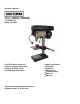
ring. Fig. 2B Secure ring with set screw (1). Fig. 2C
2.5 Rotate table assembly around column. Adjust rack retaining ring
as necessary to prevent binding of rack.
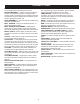
2.6 Attach crank handle (6) to shaft (7), rotate to remove slack, and
shoulder crank handle against table bracket. Secure handle with
screw. Fig. 3
2.7 Tighten table bracket locking handle (9) to secure table assembly.
Fig. 4
ASSEMBLY
Figure 1
Figure 4
Crank
Handle
Figure 2A Figure 2B
1
2
3
4
Table
Bracket