Operator’s Manual ZTS 6000 Zero-Turn Rear Engine Riders with Electric Start Model No. N ep o ro t fo du r ct io n 107.289930 (26HP Kohler Engine with 52” Mower) R CAUTION: Before using this product, read the manual and follow all its Safety Rules and Operating Instructions. For answers to your questions about this product, call: 1-800-659-5917 Sears Craftsman Help Line 5 am - 5 pm, Mon - Sat Nota: Una traducción en español de este Manual del Operador puede encontrarse en la página 37.
N ep o ro t fo du r ct io n R
TABLE OF CONTENTS Warranty Statement.....................................................3 Safety Rules & Information.........................................4 Identification Numbers................................................9 Assembly....................................................................10 Pre-Operation.............................................................13 Operation....................................................................14 Maintenance.................................
SAFETY RULES AND INFORMATION Read these safety rules and follow them closely. Failure to obey these rules could result in loss of control of unit, severe personal injury or death to you, or bystanders, or damage to property or equipment. This mowing deck is capable of amputating hands and feet and throwing objects. The triangle in text signifies important cautions or warnings which must be followed.
SLOPE OPERATION WARNING Slopes are a major factor related to loss-of-control and tipover accidents, which can result in severe injury or death. Operation on all slopes requires extra caution. If you cannot back up the slope or if you feel uneasy on it, do not operate on it. Control of a walk-behind or ride-on machine sliding on a slope will not be regained by the application of the brake.
1. Fold this page along dotted line indicated above. 2. Hold page before you so that its left edge is vertically parallel to a tree trunk or other upright structure. 3. Sight across the fold in the direction of hill slope you want to measure. 4. Compare the angle of the fold with the slope of the hill. WARNING: To avoid serious injury, operate your unit up and down the face of slopes, never across the face. Do not operate on slopes greater than 10 degrees.
SERVICE AND MAINTENANCE • Safe Handling of Gasoline • Extinguish all cigarettes, cigars, pipes, and other sources of ignition. • Use only approved gasoline containers. • Never remove the gas cap or add fuel with the engine running. Allow the engine to cool before refueling. • Never fuel the machine indoors. • Never store the machine or fuel container where there is an open flame, spark, or pilot light such as near a water heater or other appliance.
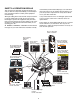
SAFETY & OPERATION DECALS This unit has been designed and manufactured to provide you with the safety and reliability you would expect from an industry leader in outdoor power equipment manufacturing. read and obeyed. Personal bodily injury can result when these instructions are not followed. The information is for your safety and it is important! The safety decals below are on your rider and mower.
IDENTIFICATION NUMBERS SA CRAFTSMAN ® Conforms to B71.1 - 1998 Safety Standards M Model No. 107.27XXXX PL Serial No. 000000XXXX E For Parts & Service Call 1-800-4MY-HOME Sears, Roebuck and Co. Hoffman Estates, IL 60179 ID Tag When contacting the service center for replacement parts, service, or information you MUST have these numbers. Record your model name/number, manufacturer’s identification numbers, and engine serial numbers in the space provided for easy access.
ASSEMBLY INSTALLING THE SEAT 3. Secure the seat to the seat base with two 5/16-18 x 3/4 serrated head bolts for the rear seat slots, and two 5/16-18 x 3/4 shoulder bolts for the front slots. 1. Raise the seat base (see Figure 1). 2. Align the holes in the seat bottom with the holes in the seat base. N ep o ro t fo du r ct io n 4. Tighten to 14-19 ft-lbs (19-25 Nm). 19-25 Nm 14-19 ft-lbs R 5/16-18 x 3/4 5/16-18 x 3/4 Figure 1.
INSTALLING THE SEAT SAFETY SWITCH 1. Squeeze the side clips of the safety switch (A, Figure 2), and insert the switch into the slot (B) in the seat bottom. Be sure to slide the switch fully forward. 2. Connect the harness terminal housing (C) to the seat switch. 3. Loop the wire tie (D) around both the switch body and the terminal housing. A A C C C Figure 2.
3. Install the hardware as shown in Figure 3. Tighten to 15-17 ft-lbs (20-23 Nm). SETTING UP THE GROUND SPEED CONTROL LEVERS NOTE: Ground speed control levers must be adjusted prior to use. Refer to the “Ground Speed Control Adjustment” section. 1. Loosen (do not remove) the hardware securing the ground speed control levers to the lever bases (see Figure 3). 2. Raise the levers, aligning the upper hole in each lever with the upper slotted hole in the lever base.
PRE-OPERATION Remove the Packaging Materials Fill-Up with FRESH Gasoline Remove the cardboard from the crate. Remove any steel branding securing the unit to the crate. Locate the manual packet. Lift the seat deck to access the fuel cap and tank. Remove the fuel tank cap and fill the tank with fresh fuel. After fueling, securely install the cap and wipe up any fuel that may have spilled. See the Operator’s Manual for fuel recommendations.
OPERATION Left Ground Speed Control Lever Right Ground Speed & Parking Brake Lever Mower Cutting Height Switch Ground Speed Levers - Ground Speed Levers DRIVE Positons START/PARK Positons Parking Brake Lever Choke (Closed) Parking Brake Lever ENGAGE Positon N ep o ro t fo du r ct io n Choke (Open) Parking Brake Lever DISENGAGE Positon Fuel Tank Cap CONTROL FUNCTIONS OFF The information below briefly describes the function of individual controls.
Choke Mower Blade Switch The yellow mower blade switch turns the mower blades on and off. To turn the mower blades ON, pull the switch up. To turn the mower blades OFF, push the switch down. Always set the engine speed control to FAST before turning the mower blades ON, and while mowing. CLOSE the choke for cold starting (pull knob up). OPEN the choke once the engine starts (push knob down). If the engine is warm, it may not require choking.
CHECKS BEFORE STARTING • Check that the crankcase oil is filled to full mark on dipstick. • Fill the fuel tank with fresh fuel. FUEL RECOMMENDATIONS For daily operation: Use only unleaded gasoline with a pump sticker octane rating of 87 or higher. Gasohol (up to 10% ethyl alcohol, 90% unleaded gasoline by volume) is approved as a fuel. Methyl Teriary Butyl Ether (MTBE) and unleaded gasoline blends (up to a maximum of 15% MTBE by volume) are approved as a fuel.
EMERGENCY STOPPING PUSHING THE RIDER BY HAND In the event of an emergency the engine can be stopped by simply turning the ignition switch to STOP. Use this method only in emergency situations. For normal engine shut down follow the procedure given in STOPPING THE RIDER AND ENGINE. NOTE: Do not disengage the transmission if parked on a slope 1.
DRIVING PRACTICE - Smooth Travel BASIC DRIVING The lever controls of the zero turn rider are highly responsive. WARNING: Never operate on slopes greater than 17.6% (10°). See SLOPE OPERATION in the safety section. Zero turn riders operate differently from other fourwheeled vehicles. The drive wheels are also your steering wheels. If you cannot drive the unit on a hill, you will not be able to steer the unit on it. Operating zero turn units on slopes requires extra caution.
Practice Turning Around a Corner Practice Turning In Place While traveling forward allow one handle to gradually return back toward neutral (see Figure 10). Practice several times before mowing. To “zero turn” means to turn in place. To turn in place, gradually move one ground speed control lever forward from neutral and one lever back from neutral simultaneously (see Figure 11). Repeat several times.
6. Turn the ignition switch OFF and remove the key. Remove the 4x4 wood blocks. 7. Insert ratchet into 3/8” (9.5 mm) square hole in idler pulley arm (A, Figure 13) and pull to release belt tension. Install the mower belt (B) as shown in Figure 13. MOWER DECK REMOVAL & INSTALLATION NOTE: Perform mower removal and installation on a hard, level surface such as a concrete floor.
MAINTENANCE MAINTENANCE SCHEDULE The following schedules should be followed for normal care of your rider and mower.
Rider Maintenance Items WARNING Move the ground speed levers to START/PARK positions, engage the parking brake, turn the mower blades OFF, turn the ignition switch OFF, and wait for all moving parts to stop before accessing the engine compartment or performing any maintenance procedures. ACCESSING THE ENGINE COMPARTMENT Figure 15. Accessing the Engine Compartment Lift up on the back edge of the seat deck to access the engine compartment (see Figure 15).
LUBRICATION Service Interval: 25 hours. Lubricate the unit at the locations shown in Figures 18 through 21 as well as the following lubrication points. Grease: • front wheel grease fittings • front wheel bushings • mower arbors Use grease fittings when present. Not all greases are compatible. Use automotive-type lithium grease.
CLEAN DECK & CHECK / REPLACE MOWER BLADES Service Interval: 25 hours or as required. WARNING For your personal safety, do not handle the sharp mower blades with bare hands. Careless or improper handling of blades may result in serious injury. LOOSEN WARNING Figure 22. Blade Removal For your personal safety, blade mounting capscrews must each be installed with a spring washer, then securely tightened. Torque blade mounting capscrew to 45-55 ft-lbs (61-75 Nm). C B N ep o ro t fo du r ct io n 1.
CLEANING THE BATTERY AND CABLES CHECK RIDER SAFETY SYSTEM WARNING Service Interval: Every 100 hours, every spring/fall, and after storage of 30 days or longer. Corrosion hazard. Batteries contain acid. Always keep the battery upright and do not spill the electrolyte. Avoid contact with skin and eyes. This unit is equipped with safety interlock switches. These safety systems are present for your safety. Do not attempt to bypass safety switches, and never tamper with safety devices.
CHECK / ADJUST PTO CLUTCH A WARNING B To avoid serious injury, perform adjustments only with engine stopped, key removed and tractor on level ground. Service Interval: 200 hours. B The Power Take Off (PTO) clutch drives the mower blades. The PTO clutch is engaged and disengaged by the mower blade switch. Check the PTO clutch adjustment every 200 hours of operation. Also perform the following procedure if the clutch is slipping, will not engage, or if a new clutch has been installed. B Figure 26.
Engine Maintenance Items Use oil classified API Service Class SG, SH, SJ or better with SAE Viscosity: CHECK ENGINE OIL LEVEL 10W-30, 30 Conventional Or Synthetic Service Interval: Before each use, and every 8 hours. 1. Turn the engine off, and set the ground speed controls to PARK. Park on a level surface. Allow the engine to cool. 5W-20, 5W-30 Conventional 5W-20, 5W-30 Synthetic* 2. Clean the area around the dip stick (C, Figure 29). 3. Remove the dip stick (C) and clean it with a paper towel.
REPLACE AIR FILTER Service Interval: Every 25 hours or two months, or as required. 1. Loosen the air filter cover knobs (A, Figure 30) and remove the cover (B). Clean out any debris from around the air filter. Inspect the condition of the sealing surfaces of the air filter element (C) and filter base (D). Replace any damaged parts. .030” (.76 mm) 2. Remove the air filter element (C). 3. Install the new air filter element with the pleated side out and seat it onto the edges of the air cleaner base (D).
SERVICE & ADJUSTMENTS GROUND SPEED CONTROL LEVER ADJUSTMENT C The control levers have three adjustments: To Adjust Control Lever Height: Pull the levers in across the operator’s lap to their DRIVE positions. Loosen the mount bolts (D, Figure 32) and raise or lower the levers to the desired position. Tighten the mounting bolts.(D). A D To Adjust Control Lever End Gap: The control lever end gap should be adjusted so that the levers do not contact each other when placed in DRIVE positions.
BRAKE ADJUSTMENT 1. Stop the unit, set the ground speed levers to START/PARK positions, set the parking brake lever to the ENGAGE position, turn the ignition OFF, and wait for all moving parts to stop. Remove the key. 3" (7.62cm) 2. Set both transmission release levers to the PUSH position. (Refer to PUSHING THE RIDER BY HAND.) D 3. Push the rider forward to make sure both transmission brakes are fully engaged and both rear wheels are locked in the stationary position (no rotation). A 4.
MOWER DECK LEVELING ADJUSTMENTS WARNING Before adjusting the mower, turn the mower blades OFF, turn the ignition switch OFF, remove the key, and allow all moving parts to stop. Disconnect the spark plug wire and fasten it away from the spark plug. Side to Side Leveling Figure 35. Orient Blades Side-to-Side If the cut is uneven, the mower may need leveling. Unequal or improper tire pressure may also cause an uneven cut. See CHECK TIRE PRESSURE. A 1.
C C B B A A Figure 38. Orient Blades Front-to-Back Figure 39. Front-to-Back Leveling A. Front Hitch Rod B. Rear Jam Nut C. Front Jam Nut Front To Back Leveling If the cut is uneven, the mower may need leveling. Unequal or improper tire pressure may also cause an uneven cut. See CHECK TIRE PRESSURE. 1. Turn the blades front-to-back as shown in Figure 38. Measure the distance from the ground to front tip of center blade, and from ground to rear tips of left hand and right hand blades (see Figure 38).
MOWER DECK WASHOUT PORT B NOTE: The washout port allows you to connect a typical garden hose to the trim side (L.H.) of the mower deck to remove grass and debris from the underside. This ensures proper and safe operation of the mower. A 1. Place the lawn tractor on a smooth level surface. WARNING Before running the mower, make sure the hose is properly connected and does not come into contact with the blades.
STORAGE STORAGE WARNING Before Storage Never store the unit (with fuel) in an enclosed, poorly ventilated structure. Fuel vapors can travel to an ignition source (such as a furnace, water heater, etc.) and cause an explosion.
TROUBLESHOOTING While normal care and regular maintenance will extend the life of your equipment, prolonged or constant use may eventually require that service be performed to allow it to continue operating properly. The troubleshooting guide below lists the most common problems, their causes and remedies. WARNING To avoid serious injury, perform maintenance on the rider or mower only when the engine is stopped and the ground speed levers are set to PARK.
Engine runs, but Transmission release levers in PUSH rider will not positions. drive. Drive belt slips. Move levers to DRIVE positions. Clean or replace belt as necessary. Belt is broken. Replace drive belt. Contact Sears Parts & Repair. Parking brake is not fully released. Contact Sears Parts & Repair. Rider drive belt slips. Pulleys or belt greasy or oily. Clean as required. Belt stretched or worn. Replace belt. Contact Sears Parts & Repair. Parking brake will not hold.
Manual Del Dueño ZTS 6000 Gire a cero los montables posteriores del motor con el arranque eléctrico No. de modelo R N ep o ro t fo du r ct io n 107.289930 (26HP Kohler Engine con segadora de 52”) PRECAUCIÓN: Este producto tiene un mot or con expulsión baja el cual funciona diferentemente a otros motores. Antes que arranque el motor, lea y comprenda el Manual del Dueño.
N ep o ro t fo du r ct io n R
ÍNDICE Declaración de Garantía ...........................................39 Reglas e Información de Seguridad ........................40 Números de Identificación........................................45 Montaje .......................................................................46 Pre-Operación............................................................49 Operación...................................................................50 Mantenimiento .......................................................
REGLAS DE SEGURIDAD Lea estas reglas de seguridad y sígalas con cuidado. No obedecer estas reglas puede ocasionar la pérdida del control sobre la unidad, lesiones severas a la persona o la muerte de usted, o espectadores, o daños a la propiedad o al equipo. Esta cubierta de la podadora es capaz de amputar manos y pies y de arrojar objetos. El triángulo en el texto denota precauciones o advertencias importantes que deben obedecerse.
OPERACIÓN EN CUESTAS ADVERTENCIA Las cuestas son un factor importante relacionado con los accidentes por pérdida de control y volcaduras, y pueden propiciar lesiones severas o la muerte. Cualquier operación en cuestas exige precauciones extremas. Si usted no puede dar marcha atrás en una cuesta o se siente inquieto en ella, no opere en ella. Nunca opere en cuestas mayores a 17.
NTE D DE LA LÍNEA 1. Doble la página a lo largo de la linea punteada como se indica arriba. 2. Sostenga la página frente a usted de modo que el borde izquierdo esté verticalmente paralelo al tronco de un árbol u otra estructura ventical. 3. Mire por encima del doblez en dirección de la pendiente que desea medir. 4. Compare el ángulo del doblez con la pendiente de la colina. ADVERTENCIA: Para evitar lesiones graves, opere la unidad hacia arriba y hacia abjo por la pendiente, nunca de un lado a otro.
• SERVICIO Y MANTENIMIENTO Manejo Seguro de la Gasolina • Apague cigarros, puros, pipas y otras fuentes de ignición. • Use sólo los contenedores aprobados para gasolina. • Nunca quite el tapón de la gasolina ni cargue combustible con el motor encendido. Permita que el motor se enfríe antes de poner combustible. • Nunca cargue combustible para la máquina en espacios cerrados.
PELIGRO, ADVERTENCIA, PRECAUCIÓN y de instrucciones en su tractor y podadora. No seguir las instrucciones puede resultar en lesiones personales al cuerpo. ¡La información es para su seguridad y es importante! Las calcomanías de seguridad abajo están sobre su tractor y podadora. CALCOMANÍAS DE SEGURIDAD Y OPERACIÓN Esta unidad fue diseñada y fabricada para ofrecerle la seguridad y confiabilidad que usted esperaría de un líder en la industria de la fabricación de equipos motorizados para el exterior.
NÚMEROS DE IDENTIFICACIÓN SA CRAFTSMAN ® Conforms to B71.1 - 1998 Safety Standards M Model No. 107.27XXXX PL Serial No. 000000XXXX For Parts & Service Call 1-800-4MY-HOME Sears, Roebuck and Co. Hoffman Estates, IL 60179 E Chapa de Identificación Cuando se ponga en contacto con el centro de servicio para obtener partes de repuesto, servicio o información usted DEBERÁ proporcionar estos números.
MONTAJE 3. Sujete el asiento a la base del asiento con dos tuercas de cabeza dentada de 5/16-18 x ¾ para los orificios traseros del asiento, y dos tuercas con traba punta de cañonera para las ranuras delanteras. INSTALACIÓN DEL ASIENTO 1. Levante la base del asiento (vea la Figura 1). 2. Alinee los orificios en la parte de abajo del asiento con los orificios en la base del asiento. N ep o ro t fo du r ct io n 4. Apriete a 19-25 Nm (14-19 lbs-pies).
INSTALACIÓN DEL INTERRUPTER DE SEGURIDAD DEL ASIENTO 1. Apriete los ganchos laterales del interruptor de seguridad (A, Figura 2), e inserte el interruptor en la ranura (B) en la parte baja del asiento. Asegúrese de deslizar el interruptor completamente hacia adelante. 2. Connecte la caja del terminal de cableado (C) al interruptor del asiento. 3. Enrosque la atadura de cable (D) en torno de ambos, el cuerpo del interruptor y la caja del terminal. A A C C C Figura 2.
3. Instale los herrajes como indica la Figura 3. Apriete a 20-23 Nm (15-17 lbs-pies). MONTAJE DE LAS PALANCAS DE CONTROL DE VELOCIDAD DE DESPLAZAMIENTO NOTA: Se debe ajustar las palancas de control de velocidad de desplazamiento antes de su uso. Consulte la sección “Ajuste de control de velocidad de desplazamiento” sección. 1. Aflojo (no retire) los herrajes que sujetan a las palancas de control de velocidad de desplazamiento a sus bases (vea la Figura 3). 2.
PRE-OPERACIÓN Retirar los Materiales de Empaque Llenar con Gasolina FRESCA Quite el cartón del cajón de embalaje. Quite el encintado de acero que sujeta la unidad al cajón de embalaje. Ubique el paquete del manual. Levante el asiento para ganar acceso al tapón de la gasolina y al tanque. Quite el tapón del tanque y llene el tanque con combustible fresco. Después de llenar el tanque, instale fijamente el tapón y limpie el combustible derramado.
OPERACIÓN Palanca de Control de Velocidad de Avance Izquierda Palancas de Velocidad Posición de DRIVE Palanca de Velocidad de Avance Derecha & Freno de Mano Palancas de Velocidad Posición de PARK Ajuste de Altura de Corte Palanca del frenco de estacionamiento Ahogador (Cerrado) Ahogador (Abierto) Palanca del freno de estacionamiento Posición DESENGRANAR N ep o ro t fo du r ct io n Palanca del freno de estacionamiento Posición ENGRANAR Tapón del Tanque de Gasolina Acelerador (Rápido) FUNCIONES DE
Interruptor de Cuchillas de la Sesgadora Ahogador CIERRE el ahogador para arrancar en frío (jale la perilla hacia arriba). ABRA el ahogador una vez que el motor arranque (empuje la perilla hasta adentro). Si el motor está caliente, es posible que no requiera el ahogador. En este caso, coloque el ahogador en OPEN (abierto) (empuje la perilla hasta adentro) mientras da marcha al motor. En la mayoría de los casos, será necesario que cierre el ahogador para poder arrancar el motor.
VERIFICACIONES ANTES DE ARRANCAR • Verifique que el aceite del cárter esté en la marca de lleno de la varilla de nivel de aceite. • Llene el tanque de gasolina con combustible fresco. RECOMENDACIONES DE COMBUSTIBLE Para operación diaria: Use sólo gasolina sin plomo donde la calcomanía de la bomba indique un octanaje de 87 o mayor. El gasohol (hasta 10% de alcohol etílico, 90% de gasolina sin plomo por volumen) está aprobado como combustible.
PARO DE EMERGENCIA 8. Cuando termine, desactive las cuchillas de la sesgadora (empuje el interruptor hacia abajo). En caso de emergencia, el motor puede detenerse simplemente girando el interruptor de encendido a STOP (paro). Use este método sólo en situaciones de emergencia. Para apagar el motor normalmente, siga el procedimiento indicado en DETENER EL MONTABLE Y EL MOTOR. 9. Detenga el montable y el motor (consulte DETENER EL MONTABLE Y EL MOTOR).
PRÁCTICA DE MANEJO - Traslado sin problemas MANEJO BÁSICO Los controles de palanca del tractor de giro cero son altamente sensibles. ADVERTENCIA: Nunca opere en cuestas mayoras a 17.6% (10°). Vea OPERACIÓN EN CUESTAS en la sección de seguridad. Los tractores de giro cero operan de modo diferente a otros vehículos de cuatro ruedas. Las ruedas de tracción también son sus ruedas de dirección. Si usted no puede conducir la unidad en una colina, usted no podrá dirigir la unidad en ella.
Práctica de dar Vuelta en una Esquina Práctica de Vuelta en el Lugar Mientras viaja hacia adelante permita que una palanca regrese gradualmente en dirección del neutral (vea la Figura 10). Practique varias veces antes de podar el césped. Hacer un "giro cero" significa girar en el mismo lugar. Para dar la vuelta en el mismo lugar, gradualmente mueva la palanca de control de velocidad hacia adelante de neutral y una palanca hacia atrás del neutral simultáneamente (vea la Figura 11). Repita varias veces.
REMOCIÓN E INSTALACIÓN DE LA CUBIERTA DE LA SESGADORA 5. Utilice el ajuste de altura de corte para alzar el cortacésped hasta que deje de descansar en los bloques de madera de 4x4. 6. Gire el interruptor de encendido a la posición APAGADO y retire la llave. Retire los bloques de madera de 4x4. 7. Inserte el trinquete en el orificio cuadrado de 9,5 mm (3/8 pulg.) del brazo de polea tensora (A, Figura 13) y tire para liberar la tensión de la correa.
MANTENIMIENTO PROGRAMA DE MANTENIMIENTO El siguiente programa debe seguirse para el cuidado normal de su tractor y podadora.
Elementos de Mantenimiento del Tractor ADVERTENCIA Mueva las palancas de velocidad de desplazamiento a las posiciones ARRANCAR/ESTACIONAR, engrane el freno de estacionamiento, APAGUE las cuchillas del cortacésped, APAGUE el interruptor de ignición, y espere que todas las piezas móviles se detengan antes de acceder al compartimiento del motor o realizar cualquier procedimiento de mantenimiento. Figura 15.
LUBRICACIÓN Intervalo de Servicio: 25 horas. Lubrique la unidad en los lugares mostrados en las Figuras 18 a 21 así como en los siguientes puntos de lubricación. Grasa: • engrasadores de la rueda delantera • bujes de la rueda delantera • árboles de sujeción de la podadora Use engrasadores cuando estén presentes. No todas las grasas son compatibles. Use grasa de litio de tipo automotriz.
LIMPIAR CUBIERTA Y VERIFICAR/ REEMPLAZAR ASPAS DE PODADORA Intervalo de Servicio: 25 horas o según se requiera. 1. Quite la cubierta de la podadora (vea REMOCIÓN DE LA CUBIERTA DE LA PODADORA en la sección de Operación). ADVERTENCIA Para su seguridad personal, no maneje las aspas afiladas de la podadora con las manos descubiertas. El manejo imprudente o indebido de las aspas puede resultar en lesiones graves. LOOSEN Afloje Figura 22.
LIMPIAR BATERÍA Y CABLES REVISAR SISTEMA DE SEGURIDAD DEL MONTABLE ADVERTENCIA Peligro de corrosión. Intervalo de servicio: Cada 100 horas, cada primavera y otoño y después de estar guardado por más de 30 días. Las baterías contienen ácido. Conserve la batería siempre de pie y no derrame el electrolito. Evite el contacto con la piel y los ojos. Esta unidad está equipada con interruptores de intercierre de seguridad. Estos sistemas de seguridad están presentes para su seguridad.
VERIFICAR/AJUSTAR EMBRAGUE DEL PTO A B ADVERTENCIA Para evitar lesiones graves, sólo haga los ajustes con el motor detenido, la llave quitada y el tractor en terreno nivelado. B Intervalo de Servicio: 200 horas. El embrague del PTO se embraga y desembraga con el interruptor PTO. El embrague suministra la energía y frena las aspas de la podadora. Verifique el ajuste del embrague del PTO cada 200 horas de operación.
Elementos de Mantenimiento del Motor de Servicio para SG, API de Use aceite oil classified APIclasificado Service Class Clase SG, SH, SJ o mejor con viscosidad SH, SJ or better with SAE Viscosity: SAE. 10W-30, Convencional o 10W-30,3030 Conventional Sintético Or Synthetic VERIFIQUE EL NIVEL DE ACEITE DEL MOTOR 5W-20, 5W-30 5W-20, 5W-30 Convencional Conventional Service Interval: Before each use, and every 8 hours. 5W-20, 5W-20,5W-30 5W-30 Sintético* Synthetic* 1.
REEMPLACE EL FILTRO DE AIRE Intervalo de servicio: Cada 25 horas o cada dos meses, o conforme sea necesario. 1. Afloje los botones de la cubierta del filtro de aire (A, Figura 30) y remueva la cubierta (B). Limpie cualquier residuo alrededor del filtro de aire. Inspeccione la condición de las superficies de sellamiento del elemento del filtro de aire (C) y de la base del filtro (D). Reemplace cualquier parte dañda. .030” (.76 mm) 2. Remueva el elemento del filtro de aire (C). 3.
SERVICIO Y AJUSTES AJUSTE DE PALANCA DE CONTROL DE VELOCIDAD Las palancas de control tienen tres ajustes: C Para Ajustar la Altura de las Palancas de Control: Jale las palancas hacia adentro, encima del regazo del operador a la posición de DRIVE. Afloje los pernos de montaje (D, Figura 32) y suba o baje las palancas a la posición deseada. Apriete los pernos de montaje (D).
AJUSTE DE LOS FRENOS 1. Detenga la unidad, coloque las palancas de velocidad de desplazamiento en las posiciones START/PARK (ARRANCAR/ESTACIONAR), coloque la palanca del freno de estacionamiento en la posición ENGAGE (ENGRANAR), apague la ignición (OFF), y espere que todas las piezas móviles se detengan. Quite la llave. 3" (7.62cm) D 2. Coloque ambas palancas de liberación de la transmisión en la posición PUSH (EMPUJAR). (Consulte CÓMO EMPUJAR LA UNIDAD MANUALMENTE.) 3.
AJUSTE DE NIVEL DE LA CUBIERTA DE LA PODADORA ADVERTENCIA Antes de realizar ajustes a la sesgadora, desactive las cuchillas de la misma, gire el interruptor de encendido para apagar el motor, quite la llave y espere a que se detengan todas las piezas móviles. Desconecte el cable de bujías y sujételo lejos de la misma. Si el corte es desigual, es posible que necesite nivelar la podadora. La causa del corte desigual puede ser que la presión de las llantas sea desigual o inadecuada.
C C B B A A Figura 38. Orientar las Aspas de Adelante hacia Atrás Figure 39. Nivelado de adelante hacia atrás A. Varilla B. Contratuerca trasera C. Contratuerca delantera NIVELADO FRONTOPOSTERIOR Si el corte es desigual, puede ser necesario el nivelado del cortacésped. La presión de neumáticos desigual o inadecuada también puede ser caso de un corte desigual. Véase COMPROBAR LA PRESIÓN DE LOS NEUMÁTICOS. E F D N ep o ro t fo du r ct io n 1.
PUERTO DE DESLAVE DE LA PLATAFORMA DEL CORTACÉSPED B NOTA: El puerto de deslave le permite conectar una manguera de jardín típica al lado de corte (izquierdo) de la plataforma del cortacésped para retirar el pasto y desechos de su parte inferior. Esto asegura el funcionamiento seguro y correcto del cortacésped. A 1. Coloque el tractor cortacésped sobre una superficie lisa y nivelada.
ALMACENAMIENTO ALMACENAMIENTO ADVERTENCIA Antes de almacenar su unidad en la temporada baja, lea las instrucciones de Mantenimiento y Almacenamiento en la sección de Reglas de Seguridad, luego realice los siguientes pasos: Nunca almacene la unidad (con combustible) en una estructura cerrada con poca ventilación. Los vapores del combustible pueden viajar a una fuente de ignición (como un horno, calentador de agua, etc.) y ocasionar una explosión.
DIAGNÓSTICO ADVERTENCIA Para evitar lesiones graves, realice el mantenimiento del tractor o la podadora sólo con el motor apagado y el freno de mano en PARK. Siempre quite la llave del encendido, desconecte el cable de la bujía y sujételo lejos de la bujía antes de empezar con el mantenimiento, para evitar que el motor arranque accidentalmente. Si lo prefiere, todos estos procedimientos pueden ser ejecutados para usted por un Centro de Partes y Reparaciones de distribudor.
El motor opera pero el tractor no avanza. Las palancas de desembrague de la Mueva las palancas a la posición de DRIVE. transmisión en posición de EMPUJAR. La banda de tracción se barre. Limpie o reemplace la banda según sea necesario. La banda está rota. Reemplace banda. Contacte Partes y Reparaciones de Sears. Freno de mano no está desaccionado. Contacte Partes y Reparaciones de Sears. Banda de tracción se barre. Poleas o la banda con grasa o aceite. Limpie según se requiera.
N ep o ro t fo du r ct io n R Repair Parts PTS - 1
Frame, Body & Seat Group ZTS 6000 -107.289930 R N ep o ro t fo du r ct io n NOTE: Unless noted otherwise, use the standard hardware torque specification chart.
Frame, Body & Seat Group 1733448ASM 1960160SM 1611710SM 1734135SM 1730186SM 1733426ASM 1733571SM 1960687SM 2860744SM 1960035SM 2860646SM 1737339AYP 1931334SM 1960368SM 1921333SM 1726025BNYP 1960694SM 1931317SM 1726306SM 1726018SM 7300752AYP 1960518SM 1935255SM 009X67MA 1960223SM 1728086SM 1931277SM 1716654SM 1960295SM 1960738SM 7102141SM 1673320SM 1733227ASM 1733965ASM 7102654YP 7301055BMYP 1960715SM 7091591SM 1728986SM 1728987SM 1674792SM QTY.
Frame, Body & Seat Group ZTS 6000 -107.289930 R N ep o ro t fo du r ct io n NOTE: Unless noted otherwise, use the standard hardware torque specification chart.
Frame, Body & Seat Group 1726400SM 1921221SM 1919381SM 7090189SM 7024340SM 7102860YP 1734320SM 1921977SM 1933988SM 1727810ASM 1726390SM 1715962ASM 1925003SM 1733393ASM 1687021SM 1960686SM 1920415SM 1931942SM 1960534SM 7070814SM 1921880SM 1734392ASM 1924940SM 1930645SM QTY. 1 1 1 1 1 1 1 5 4 1 2 1 6 1 1 9 1 1 1 1 2 2 2 1 DESCRIPTION BUSHING, Fuel CAPSCREW, 5/16, 18 x 1-1/2 WASHER, 5/16, .34 ID x 1 OD x .
Engine Group - 26HP Kohler ZTS 6000 -107.289930 R N ep o ro t fo du r ct io n NOTE: Unless noted otherwise, use the standard hardware torque specification chart.
Engine Group - 26HP Kohler 7027266SM 1918199SM 1708264SM 2832747SM 1686880SM 2828635SM 1924940SM 7101717SM 2154096SM 7101716SM 1931277SM 1924856SM 1921332SM 7300970ASM 1726498SM SV735-0018 7075449SM 1960295SM 7300971ASM 1960368SM 1727939ASM 7102318SM 1936228SM 1917356SM 1731214SM 7102344SM 7090390SM 7091630SM 7090999SM 7091195SM 7100529SM 1735196SM 7029900SM 1930591SM 7900020SM 1931277SM QTY.
Transmission Group ZTS 6000 -107.289930 R N ep o ro t fo du r ct io n NOTE: Unless noted otherwise, use the standard hardware torque specification chart.
Transmission Group 1960223SM 1919381SM 1703900SM 1960684SM 1727555SM 1727556SM 1727831SM 1930650SM 1927120SM 1923141SM 1919326SM 1717024SM 1733913SM 1960268SM 1960758SM 1733305ASM 1921719SM 1725550SM 1733914SM 1931277SM 5020601SM 1733309ASM 1733351SM 1733352SM 1733302ASM 1960687SM 5025396SM 1728976SM 1924874SM 1927557SM 7091501SM 1732224SM 1930645SM 1924356SM 1921210SM 1734316SM 1729007SM 1733303ASM 1721133SM 1924940SM 1923701SM 1931942SM 1960759SM QTY.
Transmission Group ZTS 6000 -107.289930 R N ep o ro t fo du r ct io n NOTE: Unless noted otherwise, use the standard hardware torque specification chart.
Transmission Group REF NO PART NO. ZTS 6000 -107.289930 QTY. 1933988SM 1728073SM 1728074SM 1728075SM 1728060SM 1687329SM --1728076SM 1716622SM 1735490SM 1735491SM 1735483SM 2 2 2 1 1 2 2 2 1 1 1 1 2 58 1735482SM 2 DESCRIPTION NUT, Push Pal, 5/16 PULLEY, 4-1/2" Transmission FAN, 6" Transmission PARKING BRAKE ARM ASSEMBLY, Transmission HYDRO SEAL KIT HUB REPLACEMENT KIT (Includes Ref. Nos. 52 & 53) HUB, EZT Transmission (Included in Ref. No. 51) NUT, EZT Transmission (Included in Ref. No.
Controls Group ZTS 6000 -107.289930 R N ep o ro t fo du r ct io n NOTE: Unless noted otherwise, use the standard hardware torque specification chart.
Controls Group 1726410SM 1727796ASM 1960686SM 1720452SM 1919381SM 1960086SM 1917356SM 1727926ASM 1727927ASM 1931338SM 1931335SM 1727663ASM 1727919SM 1728010ASM 1728009ASM 7300992AYP 7091298YP 7015761YP 1960027SM 7091591SM 7300993AYP 7090188SM 1920161SM 1722460SM 7072403YP 7102567YP 7102551YP 1727814ASM 1709314SM 1729277SM 1960694SM 1925003SM 1727933ASM 1726839SM 1960717SM 1931277SM 1960723SM 1666697SM 1921977SM 1715025SM 1919438SM 1727603ASM 1921221SM QTY.
Controls Group ZTS 6000 -107.289930 R N ep o ro t fo du r ct io n NOTE: Unless noted otherwise, use the standard hardware torque specification chart.
Controls Group REF NO PART NO. 1727918SM 1703805SM 1725927SM 7022886YP QTY. 2 2 1 1 DESCRIPTION SHOCK ABSORBER RING, Klipring Extension (for .500 Dia. Shaft) SHAFT, Cross SWITCH, Push Button (Parking Brake Switch) R N ep o ro t fo du r ct io n 44 45 46 47 ZTS 6000 -107.
Electrical Group ZTS 6000 -107.289930 R N ep o ro t fo du r ct io n NOTE: Unless noted otherwise, use the standard hardware torque specification chart.
Electrical Group REF NO PART NO. ZTS 6000 -107.289930 QTY.
Lift Group ZTS 6000 -107.289930 R N ep o ro t fo du r ct io n NOTE: Unless noted otherwise, use the standard hardware torque specification chart.
Lift Group 1733535ASM 009X67MA 1931277SM 094067MA 1960170SM 1960074SM 1704420SM 1960687SM 1666294SM 1731894SM 1734217SM 1733356ASM 1673796SM 1734336ASM 1931337SM 1733536ASM 1960757SM 1921319SM 1733513SM 1722460SM 1733572SM 1733454SM 1930644SM 1931335SM 1668344SM 1733533ASM 1916950SM 1924940SM 1930645SM QTY. 1 2 5 2 2 4 2 2 2 2 2 1 1 1 1 1 1 1 1 3 1 1 2 1 1 1 2 2 2 DESCRIPTION ARM, Mower Lift L.H.
Wheel & Tire Group ZTS 6000 -107.289930 R N ep o ro t fo du r ct io n NOTE: Unless noted otherwise, use the standard hardware torque specification chart.
Wheel & Tire Group REF NO PART NO. 1726383SM 7091772SM 7035359SM 1734013SM 7090839SM 7104428YP 2172353SM 2177725SM 1739281YP QTY. 2 2 2 2 2 2 2 8 2 DESCRIPTION WHEEL & TIRE ASSEMBLY, 18 x 8-1/2-8 CAPSCREW, Hex Head TUBE, Caster Wheel Spacer WHEEL & TIRE ASSEMBLY, 11 x 4-5 NUT, Hex Center Lock FITTING, Lube VALVE STEM & CAP NUT, Hex Lug, 7/16-20 BUSHING, 0.632ID 1.377OD, .62 R N ep o ro t fo du r ct io n 1 2 3 4 5 6 7 8 9 ZTS 6000 -107.
Decals Group ZTS 6000 -107.289930 R N ep o ro t fo du r ct io n NOTE: Unless noted otherwise, use the standard hardware torque specification chart.
Decals Group 1704277SM 1704276SM 7103181YP * 1720543SM 7103145YP 7102575YP 7102574YP 1726638SM 7103215YP 1734335SM 7103193YP 1734270SM 7103067YP 7103068YP 7102576YP 7103214YP 1734276SM 7103174 7103146YP 1734672SM 1734273SM 7102578YP QTY.
52" Mower Deck - Clutch & Support Group R N ep o ro t fo du r ct io n NOTE: Unless noted otherwise, use the standard hardware torque specification chart. PTS - 24 ZTS 6000 -107.
52" Mower Deck - Clutch & Support Group 1922130SM 1924940SM 1736540YP 1736438BMYP 1931211SM 1927557SM 1931335SM 1737229BMYP 1737439BMYP 1736539YP 1960170SM 1736896YP 1960687SM 1736075BMYP 1736074BMYP 1931277SM 1931334SM 1737417YP 1736071BMYP 1736081YP 1930644SM 1960170SM 1913744SM 1960074SM 1960379SM 1960686SM 1930591SM 1736070BMYP 1960373SM 1737219BMYP 1736398BMYP 1736397BMYP 9344MA 1714255SM 1736437BMYP 1736439BMYP 1736516YP 1737415YP 1933685SM 1960339SM QTY.
52" Mower Deck - Housing & Arbor Group R N ep o ro t fo du r ct io n NOTE: Unless noted otherwise, use the standard hardware torque specification chart. PTS - 26 ZTS 6000 -107.
52" Mower Deck - Housing & Arbor Group 1923027SM 1656916SM 1735733YP 1736445YP 1735326YP 1735573YP 1735323YP 1735399YP 1735328YP 1735716YP 1736518BMYP 1664847SM 1735447YP 1735735BNYP 1735752YP 1736364YP 1736366YP 1736505YP 1736898YP 1737252AYP 1737279BMYP 1737418BMYP 1920676SM 1930600SM 1931277SM 1931334SM 1960373SM 1960766YP 7012542YP 1737359BMYP 1737439BMYP 1931277SM 1736519BMYP 1931333SM QTY.
Kohler Engine Parts - SV735-0018 ZTS 6000 - Model No. 107.
Kohler Engine Parts - SV735-0018 REF. PART ZTS 6000 - Model No. 107.289930 DESCRIPTION REF.
Kohler Engine Parts - SV735-0018 ZTS 6000 - Model No. 107.
Kohler Engine Parts - SV735-0018 REF. PART ZTS 6000 - Model No. 107.289930 DESCRIPTION REF.
Kohler Engine Parts - SV735-0018 ZTS 6000 - Model No. 107.
Kohler Engine Parts - SV735-0018 REF. PART ZTS 6000 - Model No. 107.289930 DESCRIPTION REF. DESCRIPTION FUEL SYSTEM - Group 8 1 32 853 12-S KIT, CARBURETOR W/GASKETS (INCLUDES 2,3) 2 24 041 52-S GASKET, CARBURETOR 3 24 041 14-S GASKET, AIR CLEANER BASE 4 M-629105-S STUD, M6X1.0X106 5 M-641060-S NUT, FLG M6X1.0 6 25 237 14-S CLAMP, HOSE 1/2" 6 25 237 14-S CLAMP, HOSE 1/2" 7 25 111 34-S LINE, FUEL (24"-CUT TO LENGTH) 11 24 086 12-S SCREW, TAP M6X1.
Kohler Engine Parts - SV735-0018 ZTS 6000 - Model No. 107.289930 Decals - Group 12 Air Intake/Filtration - Group 10 10 1 27 9 8 4 1 Artwork is representative. Actual labels may differ depending on model and specification number.
Kohler Engine Parts - SV735-0018 REF. PART ZTS 6000 - Model No. 107.289930 DESCRIPTION REF. PART DESCRIPTION ENGINE CONTROLS - Group 9 1 24 211 03-S BOLT, RD HD SQ NECK M6X1.0X25 3 M-641060-S NUT, FLG M6X1.0 4 24 089 01-S SPRING, LINKAGE 5 25 158 08-S BUSHING, LINKAGE RETAINING 6 24 079 04-S LINKAGE, THROTTLE 7 25 158 11-S BUSHING, THROTTLE LINKAGE 12 M-645016-S SCREW, FLG THD FRM M6X1.0X16 14 12 237 01-S CLAMP, CABLE 15 24 086 43-S SCREW, LBD THD FRM M5x0.
Hardware Identification & Torque Specifications Common Hardware Types Torque Specification Chart Hex Head Capscrew FOR STANDARD MACHINE HARDWARE (Tolerance ± 20%) Washer Hardware Grade Lockwasher Carriage Bolt No Marks SAE Grade 2 Hex Nut Size Of Hardware Standard Hardware Sizing 8-32 8-36 10-24 10-32 1/4-20 1/4-28 5/16-18 5/16-24 3/8-16 3/8-24 7/16-14 7/16-20 1/2-13 1/2-20 9/16-12 9/16-18 5/8-11 5/8-18 3/4-10 3/4-16 7/8-9 7/8-14 1-8 1-12 When a washer or nut is identified as 1/2”, this is the
PTS - 37 N ep o ro t fo du r ct io n R
PTS - 38 N ep o ro t fo du r ct io n R
Repair Protection Agreements Acuerdo de Protección de Reparaciones Congratulations on making a smart purchase. Your new Craftsman® product is designed and manufactured for years of dependable operation. But like all products, it may require repair from time to time. That’s when having a Repair Protection Agreement can save you money and aggravation. Felicidades por su compra inteligente. Su nuevo producto de Craftsman® fue diseñado y fabricado para años de operación confiable.
Get it fixed, at your home or ours! Your Home For troubleshooting, product manuals and expert advice: www.managemylife.com For repair – in your home – of all major brand appliances, lawn and garden equipment, or heating and cooling systems, no matter who made it, no matter who sold it! N ep o ro t fo du r ct io n For the replacement parts, accessories and owner’s manuals that you need to do-it-yourself.