
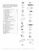
Operator`s manual


5. Cleanthe small piecesof styrofoam off
the saw.
6. Place the motor on the center channel of
the saw.
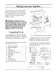
7. Remove the lock nut and flat washer from
the motorpivot support. (Figure 15)
Fig. 15
8. Slide the motor onto the motor pivot sup-
port. Make sure the motor is firmly in place.
9. Put the flat washer and locknut back in
place and tighten using a 3/4 inch socket
wrench. Move the bevel lock back and forth
as you tighten the locknut. Do not over-
tighten.
10. Push the bevel lock to the left as far as it
will go. (Figure 16)
If the bevel lock touches the left side of the
yoke, unlock the bevel lock and tighten the
Iocknut on the motor pivot support. Then go
to step 9 and repeat, or
If there is more than 1/16 inch gap between
the bevel lock and the left side of the yoke,
unlock the bevel lock and loosen the locknut
on the motor pivot support. Then go to step
J9 and repeat.
12. Repeat steps 9-10 until the bevel lock
will not touch the left side of the yoke, and
the gap is not more than 1/16 inch.
13. Lock the bevel lock.
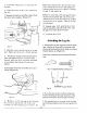
Attaching the Leg Set
1. Mount floor leveler support brackets inside
legs. Line up the three tabs on brackets with
slot on leg and tap into place. Make sure lip on
bracket points up. (Figure 18')
Install the remaining three brackets the same
way.
Fig. 17- Support Bracket, Leveling Foot
Support Bracket
Fig. 18
Fig. 16
I 1. If there is a 1/16 inch gap or less between
the bevel lock and the left side of the yoke
(and they are not touching), go to step 13, or
2. Put a hex nut on each of the leveling feet.
Put the leveling feet through the holes in the
bottom of the floor leveler support bracket.
10
3. Put another hex nut on each of the leveling
feet and hand-tighten until they are against the
leg.