Sears owners manual MODEL NO. 113.19761 Serial Number Model and serial number may be found at the front of the base. You should model record and serial CRRFTSMRNo both number in a safe place for future use. IO-INCH RADIAL CAUTION: Read and SAW GENERAL • assembly ADDITIONAL SAFETY • operating INSTRUCTIONS carefully Sold by SEARS, Part No. 63783 • repair ROEBUCK AND parts CO., Chicago, IL. 60684 U.S.A. Plinted in U.S.A.
FULL ONE YEAR WARRANTY ON CRAFTSMAN If within one year from workmanship, Sears will the date of purchase, this Craftsman repair it, free of charge. WARRANTY OR SERVICE SERVICE CENTER IS AVAILABLE THROUGHOUT This gives you specific warranty legal BY SIMPLY THE UNITED rights, Radial RADIAL SAW Saw fails due to a defect CONTACTING STATES. THE and you may have other rights NEAREST which in material SEARS vary from or STORE state to state. SEARS, ROEBUCK AND CO.
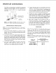
additional safety instructions --A large proportion of saw accidents is caused by use of the wrong type blade, dull, badly set, improperly sharpened cutting tools, by gum or resin adhering to cutting tools, and by sawblade misalignment out-of-parallel with the fence. Such conditions can cause the material to stick, jam {stall the saw) or "KICKBACK" at the operator. NEVER ATTEMPT TO FREE A STALLED SAW BLADE WITHOUT FIRST TURNING THE SAW "OFF".
additional removed accessory instructions safety from shaft for radial the saw arbor before using the (rear end of the saw motor). NEVER Therefore, potential (B) RIPPING along the fence and parallel to the fence). 1. thru the sawblade (sawblade Never apply the feed force to the section of the workpiece that will become the cut-off (free) piece. Feed force when ripping must always be applied between the saw blade and the fence . . . use a "PUSH work. STICK" (see pg.
(C)CROSSCUTTING 1. ALWAYSRETURNTHECARRIAGE TO THE FULLREARWARD POSITION ATCONCLUSION OFEACHCROSSCUT TYPEOPERATION. Never remove yourhandfromtheYokeHandle unless the carriage is in this position.Otherwise thecutting tool mayclimbup on the workpiece and be propelled towardyou. 2. Placeguardin horizontalpositionand adjust antikickback pawls tojustclearthetopofthefence or workpiece, whichever is higher.Thisprovides additional guarding. 3.
electrical connections An adapter as shown below plugs to 2-prong receptacles. extending from the adapter permanent outlet box. ground such GROUNDING as to __ a properly 4.
LOCATIONS MITER AND FUNCTIONS INDICATOR ARM BEVEL INDEX RIP SCALE OF CONTROLS CONTROL LEVER LEVER INDICATOR SWIVEL L_ATCH LEVER ON-OFF SWITCH WITH KEY LOCK NG WHEEL TABLE CLAMP GUARD CLAMP SCREW ELEVATION CRANK \ CARRIAGE LOCK KNOB LOCK HANDLE MANUAL ANTIKICKBACK_ SPREADER ADJUSTING WING SCREW BRAKE SHAFT ANTIKtCKBACK AND SPREADER ASSEMBLY BEVEL INDEX INDICATOR 7 BEVEL LOCK LEVER
CONTENTS Guarantee .................................... General Safety Instructions for Power Tools ......... Additional Safety Instructions for Radial Saws ....... Electrical Connections .......................... Assembly and Alignment ........................ Unpacking and Preassembly ..................... Alignment Procedure ......................... assembly 2 2 3 5 8 8 11 Location and Functions of Controls ............... Basic Saw Operations ..........................
REMOVE SKIDS FROM BASE MOUNT SAW TO CRAFTSMAN BASE, STEEL LEGS, OR FLAT BENCH Make sure Elevation Crank has proper clearance to rotate. The saw must be bolted down. Position your saw to slope slightly rearward, so when the carriage is installed it will not roll forward due to gravity. I ATTACH ELEVATION CRANK. Be sure setscrew is tightened ELEVATE Remove ARM shipping on flat of shaft. TO ITS MAX. block HEIGHT. and discard.
assembly and alignment BE positive switch is "OFF" thru-out entire procedure. and power cord unplugged _J__._ REMOVE CARRIAGE AND TAG. Read and discarding. STOP SCREW, LOCKWASHER understand warning tag before WARN ING _:_ -.,_-----_,--- TAG LOCKWASHER i_...._./STOP L_ SCREW "_'-'- HEX 'L" WRENCH SUPPLIED LOCK ARM BEFORE PROCEEDING. HOLDING HANDS, CARRIAGE CAREFULLY CARRIAGE ONTO THE ASSEMBLY START AND TRACKS.
ALIGNMENT PROCEDURE IMPORTANT: SQUARE IN ORDER TO OBTAIN MAXIMUM CUTTING ACCURACY, THE FOLLOWING SIX STEPS MUST BE CAREFULLY FOLLOWED. BECOME THOROUGHLY FAMILIAR WITH THESE STEPS SO THAT YOU CAN ALWAYS MAINTAIN YOUR SAW IN PROPER ALIGNMENT. THE ACCURACY OF EACH ADJUSTMENT IS ALWAYS DEPENDENT UPON THE A CCURA C Y OF THE PRECEDING ADJUSTMENT. After following the 6 step assembly procedure and the Basic Saw operation Trouble Shooting section if any difficulty when performing any sawing operation.
assembly and alignment FRONT IN "_\_._/!k_J" _ INSTALLATION OF FRONT (WORK) TABLE. T-NUT 1. Place front table board upside down on a workbench or on the floor Drive T-nut into the hole that is not counterbored. 2. Align the counterbored holes with matching holes in support channels. Install the five 17/64 inch flat washers, and four ¼20 x 1 inch Pan-Head machine UPSIDE HOLE HOLD /" _ DOWN FOR POSITION) TABLE DOWN BOTTOM SCREWS T-NUT (TYPICAL) 1/4-20 PAN i TABLE X°1-3/4 HE.
-> 2. 3. Loosen (2) ¼ - 20 Gib set screws on the left side at the rear of the column support. Elevate, and then lower the binds and elevation is difficult plated nuts on front side of the column support until you achieve smooth but firm elevation. (b) If the column moves side-to-side within the column support, tighten the two 5/16 - 18 plated nuts until movement disappears -- elevation should be smooth and firm. 4.
assembly and alignment 3. Lower arm until saw blade Lock the yoke clamp handle 4. Place a framing square on the table as shown and position the blade and square until the leg of the square just contacts a tooth of the blade. Mark this tooth. 5. When the carriage is moved back and forth on the arm, the marked tooth should just touch the square at all points. If marked tooth moves into square or away from square the following adjustments are required: (3) 3/8 16 set screws in arm latch table. a.
STEP FOUR SQUARING SAW BLADE TO (WORK) TABLE NOTE: If alignment procedure step one was not performed, this adjustment can not be accomplished. 1. Place a framing square on the table with the short leg against the saw blade. Do not allow the square to rest against a "set-out" tooth; it must rest flat against the blade side. 2. RIP FENCE \ If the saw blade is square with the table top (no visible gap appears between the saw blade and square) and no adjustment is required.
assembly 3. To correct and alignment "heel" condition left proceed hand carriage as follows: a. Remove b. Loosen the yoke clamp c. Loosen (slightly) the two d. Rotate the yoke assembly until saw blade and square is eliminated. e. Lock yoke clamp hex-head screws. handle f. Recheck and install g. Loosen for "heel" carriage cover. HEX HEAD SCREWS handle. hex-head and screws. gap between retighten carriage the the two cover. lock knob.
SCREW STEP SIX INSTALLING INDICATORS. 1. AND ADJUSTING RIP SCALE I NOTE: The rip scale and pointer is intended used for quick settings. For greater accuracy, direct measurement between blade and fence. to be take I _I'_, RIP SCALE JI_IL INDICATOR Pre-assemble indicator and twin nut, loosen but do not remove the two screws which attach left hand carriage b° Tilt Tighten d. cover. carriage cover and install carriage attaching rip indicator as shown. screws.
assembly and alignment r ALIGNMENT WARNING: OF SPREADER NEVER Install a. RIPPING. POSITION ANTIKICKBACK ASSEMBLY POSITION ANTIKICKBACK PAWLS OR SPREADER. 2. FOR THE GUARD OR WITH POWER ON; NOR PAWLS BY GRASPING Blade Guard. Sight (wsually) to check for proper alignment of spreader with saw blade as shown. If the spreader is not aligned, adjust it as follows: (1) Loosen two spreader. (2) Rotate hex nuts with fingers until is directly in line with saw blade.
locations and functions of controls The versatility of the Radial Saw is due, in part, to its controls, and these are the keys to its successful operation. Learn to use the controls for all operations before actually starting . to saw. A series of six diagrams is located on the top surface of the arm. These designate the controls that must be used in basic set-ups and operating procedures.
locations Depth and functions of controls of Cut (Elevation) a. The diagram shows the elevation crank used to raise and lower the saw blade. b. Clockwise rotation raises the which saw-blade bevel-index is 2. Angle are: bevel lock lever c. The bevel index lever automatically indexes the motor at 0 °, 45 ° and 90 ° . Move bevel index lever to the left while positioning the blade, then it. At any other position it does not engage.
WARNING: FOR YOUR OWN SAFETY ALWAYS LOCK THE SWITCH "OFF" WHEN SAW IS NOT IN USE. REMOVE KEY AND KEEP IT IN A SAFE PLACE . . . ALSO IN THE EVENT OF A POWER FAILURE (ALL YOUR LIGHTS GO OUT) TURN SWITCH OFF. LOCK IT AND REMOVE THE KEY THIS WILL PREVENT THE SAW FROM STARTING UP AGAIN WHEN THE POWER COMES BACK ON. 2. The antikickback ripping operations and spreader assembly and is adjustable to the thickness of the board being in the guard secures the assembly. These adjustments ripped.
HAVE YOU FOLLOWED ALL SIX STEPS OF THE ALIGNMENT PROCEDURE? IF YOU HAVE NOT FOLLOWED THEM IN THEIR PROPER SEQUENCE, YOU CANNOT EXPECT A CCURA TE CUTTING RESUL TS. THIS EDGE OF BOARD AGAINST FENCE FOR ALL CUTS / In addition to the proper alignment of your saw, you must also become familiar with the following practices in order to expect the best results. I. Edge of workpiece must be as straight which is placed against fence as the long side of your framing FENCE , / I. square. 2.
basic saw operations REQUIREMENTS FOR CROSSCUT Board position (stationary) laying flat on table top. against (OPERATIONS rip fence 1 THROUGH (guide) and 4) 1, Arbor nut must be tight in horizontal position. 2. Arm 3. Adjust the antikickback assembly so the pawls just clear the workpiece or the fence, whichever is higher. 4. Work must be held firmly against table and fence. For workpieces thicker than the fence is high, install a higher fence (at least workpiece thickness).
basic saw operations OPERATION No. 2 - MITER CROSSCUT Miter crosscutting is the process of sawing a board at any angle other than a 90 ° (square) cut. The 45 ° miter angle is a popular one, since two boards cut to 45 ° can be assembled to form a 90 ° corner for producing a square or rectangular frame. The radial arm is set to the desired angle of cut; yoke and bevel settings indexed at 0 ° (and locked) as in square crosscutting.
REQUIREMENTS WHEN (OPERATIONS lock 6) 1. Carriage 2. Radial arm must be locked in 0 ° position. 3. Work must be held feeding through. against 4, Guard, spreader, and antikickback (AKB) mechanism must be properly set. OBSERVE INSTRUCTIONS IN PARAGRAPH, "POSITIONING GUARD, AND ANTIKICKBACK AND SPREADER ASSEMBLY FOR RIPPING" UNDER "LOCATION AND FUNCTION OF CONTROLS". 5. Blade should 6. When ripping knob RIPPING 5 AND must be locked.
2. £ince the work is pushed along the fence, it must have a straight edge in order to make sliding contact with the fence. Also, the work must make solid contact with the table, so that it will not wobble. Provide a straight edge, even if this means temporarily nailing of an auxiliary straight-edged board to the work. If the workpiece is warped, turn [he hollow side down. 3.
adjustments ADJUSTING 1. to compensate for wear BEVEL LOCK LEVER The purpose of this lever is to lock the motor at any angle. To adjust, remove the set screw with wrench as shown. Use the bevel lock lever as a wrench to tighten the clamp bolt. Do Not Over Tighten. Replace bevel lock lever in locked position and tighten the set screw. BEVEL LOCK LEVER / l 1/8 _ YOKE LOCK HANDLE 1. IN LOCKED POSITION ADJUSTMENT.
adjustments to compensate for wear 3/8-]6 ARM TO COLUMN With the release vertical arm The arm should adjust. a. control lever position, the arm play in the arm. fit unlocked should snugly and move firmly on the column. in index with If not, no then Remove four (4) screws from rear cover plate and tighten evenly top two 3/8-16 bolts, until arm moves firmly and there is no vertical or horizontal movement in the locked or unlocked. arm when arm b.
ARMLOCKADJUSTING WHEEL Arm control lever operates a brake shoe that releases the arm, and automatically releases the pip for O° & 45 ° miter settings. The lock action should amount of effort must arm. NOTE: Lever must locks and arm index feel tight and secure. Considerable be applied to the lever to lock the be in unlocked position while making adjustment. TIGHTEN If adjustment is required, under front of the arm clockwise to loosen.
trouble-shooting WARNING: SOURCE REMOVE BEFORE POWER TROUBLE CORD FROM POWER SHOOTING. NOTE: Changing one adjustment will effect another, best to perform all of the alignment procedures correcting any one problem. so it is when The usual operating "troubles" are listed in the following paragraphs with the necessary corrections listed. RADIAL SAW DOES NOT 45 ° MITER CROSSCUTS. a. Looseness support. between Align as described Step Two. b. Crosscut Refer Section c. d.
trouble-shooting IN 5. WOOD DOWN a. BINDS, OR STOPS Dull blade or warped Sharpen attempted b. MOTOR SLOWS TOP board. Avoid the e. Carriage Assembly BOARD RIPPING. PULLS Saw Blade WORKPIECE in AWAY action explained NOT \ FROM in adjustments HEEL J TO WITH FEED FENCE HEEL RIGHT: INCORRECT FENCE TO LEFT: I NCORR ECT WHEN is the same as in paragraph c. SPREADER WHEN preceding RIPPING. Dirty tracks. Clean Tracks. b. Bad Bearing.
MOTOR TROUBLE - SHOOTING CHART NOTE: Motors used on wood-working tools are particularly susceptible to the accumulation of sawdust and wood chips and should be blown out or "vacuumed" frequently to prevent interference with normal motor ventilation. TROUBLE Motor will not run. Motor will not run and fuses "BLOW". PROBABLE CAUSE 1. Low voltage. 1. Check 1. Short circuit in line, cord or plug. 1. Inspect line, cord and plug for damaged insulation and shorted wires. 2.
maintenance and lubrication MAINTENANCE NO LUBRICATION Do not lubricate carriage ball bearings or motor these are sealed ball bearings and require lubrication. WARNING: FOR YOUR OWN SAFETY, TURN SWITCH "OFF" AND REMOVE PLUG FROM POWER SOURCE OUTLET BEFORE MAINTAINING OR LUBRICATING YOUR SAW. When you receive your new Craftsman radial saw, it requires no lubrication. The radial saw has been partially aligned and all bearings are lubricated and sealed for life.
8 6 1 m| ! I 36 38 35 37 21 22 4 3O 23 26 44 45 Figure 1 I 43--_
PARTS LIST FOR CRAFTSMAN MODEL NUMBER 10-INCH RADIAL 113.19761 SAW Always order by Part Number - Not by Key Number. FIGURE Key No. Part No. Key No. Description T 1 2 3 4 5 6 7 8 9 10 11 12 13 14 15 16 17 18 19 20 21 22 23 24 25 63518 37818 60339 60353 63625 63719 63717 63718 63686 125525 436594 STD 551010 63671 STD 541110 STD 551131 9421620 STD 512520 63721 63432 63720 102711 STD 551025 STD 512510 Hardware Part No. Description • Cord, with Plug Relief, Strain *Screw, Hex Hd.
PARTS LIST FOR CRAFTSMAN MODEL NUMBER 10-INCH RADIAL 113.19761 SAW uJJl "0 43 41 42 44 / / /35 / 28 28// 11 281 I / / / 46 .
PARTS LIST FOR CRAFTSMAN MODEL NUMBER FIGURE 2Key No. 1 2 3 4 5 6 7 8 9 10 11 12 13 14 15 16 17 18 19 20 21 22 23 24 25 26 27 28 29 30 31 Part No. STD 601105 63661 63786 STD 510605 120399 63657 63655 63658 63656 STD 551031 STD 551131 STD 523107 63778 60336 63782 63777 60040 STD 541462 STD 551062 30567 30530 63779 63528 63659 63660 30521 63641 STD 541231 30495 30494 60175 *Standard Type "T" Pan Hd. 10-32 x 1/2 Part No. Cover, R.H.
r,,3 30 49 -'-'_\\ k \ 31 °- ,, _ zi; "_.. .8 39 33 "_.
PARTS LIST FOR CRAFTSMAN MODEL NUMBER FIGURE 3- Key No. Part No. Key No. 1 2 3 4 5 6 7 8 STD 503705 63623 60330 63611 63610 STD 572510 63612 9416187 *Screw, Soc. Set 3/8-16 x 1/2 Latch, Arm Ring, Retaining 3" Tube Assembly Gib, Column Tube *Pin, Roll 1/4 x 1 Nut, Elevation Screw, Type "T" Hex Washer Hd. 5/16-18 x 3/4 9 10 11 12 13 14 15 16 17 18 STD 523110 60078 STD 541037 STD 551137 60340 STD 523712 186648 60329 STD 523120 60336 *Screw, Hex Hd. 5/16-18 x 1 *Screw, Hex Hd.
repair parts PARTS LIST FOR CRAFTSMAN MODEL NUMBER FIGURE Key No. 1 2 3 4 5 63626 63629 63631 63628 9420417 6 7 63627 63632 Housing, Pin Pin, Arm Index Shoe, Arm Lock Spring, Tension *Screw, Type "T" 1/4-20 x 5/8 Guide Rod, Index Hex Washer Hd. 63630 STD 551025' 637O9 63725 63716 63633 60332 STD 541025 STD 551225 63635 63634 9417711 Spring, Arm Lock *Washer, 17/64 x 47/64 x 1/16 Spring, Clip .
PARTS LIST FOR CRAFTSMAN MODEL NUMBER 10-INCH RADIAL 113.19761 SAW 4 5 6 7 1 9 17 15 14 16 10 12 11 13 FIGURE Key No. Part No. 5 - GUARD Key No. Description 1 2 3 4 5 6 63681 Guard 120399 *Nut, Square, 5/16-18 63541 Bar, Anti Kickback 6354O Guide, Anti Kickback STD 551010 *Washer, 13/64 x 5/8 x 1/32 STD 601103 *Screw, Type "T" Pan Hd. 7 8 60219 Screw, Wing 5/16-18 STD 541231 *Nut, Hex.
NOTES 42
NOTES
Sears owners manual SERVICE MODEL NO. 113.19761 HOW TO ORDER REPAIR PARTS IO-INCH RADIAL SAW Now that you have purchased your 10-inch radial saw, should a need ever exist for repair parts or service, simply contact any Sears Service Center and most Sears, Roebuck and Co. stores. Be sure to provide all pertinent facts when you call or visit. The model number of your 10-inch radial saw will be found on a label attached to your saw, at the front of the base.