Save This Manual For Future Reference _AIRS Operators Manual MODEL NO. 113.198111 10" RADIAL SAW WITH LEG SET ,,,,,,,,,,,,,,,, Serial Number Model and serial numbers may be found at the rear of the base. You should record both model and serial number in a safe place for future use. I:RRFTSMRN 10-INCH RADIAL SAW CAUTION: • Assembly • Operating • Repair parts READ ALL INSTRUCTIONS CAREFULLY Sold by SEARS, Part No. SP5101 ROEBUCK AND CO., Chicag_o. IL. 60684 U.S.A. Printed in U.S.A.
ii FULL ONE If within one workmanship, YEAR WARRANTY year from the date of purchase, Sears will repair il, tree of charge. WARRANTY SERVICE CENTER/DEPARTMENT IS AVAILABLE THROUGHOUT This warranty applies This gives you warranty only while this specilic SEARS, legal Craftsman Radial Saw BY SIMPLY CONTACTING THE UNITED STATES. product ROEBUCK ON CRAFTSMAN this rights AND is used in the and CO.
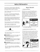
Safety Information The operator's manual contains safety information, instructions and signs for your protection against serious injuries, including: Loss of fingers, hand, with the saw blade. arm or leg from contact Eye injuries, including being blinded from being hit by a thrown workpiece, workpiece chips or pieces of the saw blade. Impact injuries, including broken bones and internal organ damage, from being hit by a thrown workpiece, workpiece chips or pieces of the saw blade. Major Hazards 1.
3. Wrong Way Feed Wrong way feed is feeding the workpiece into the end of the saw ,Mth the anti-kickback pawls. The workpiece can be grabbed by the blade and pul! your hands into the blade before you can let go or pull back. Fingers, hand or arm can be cut off. can be blinded Wear safety goggles. Fig. 6 Safety Goggles Safety Sign Wrong Way Feed. Fingers,hand, arm can De cut off. Feed into infeed end of saw.
Personal Saw Safety 1. Wear safety goggles labeled "ANSI Z87.1" on the package. Do not wear regular glasses, they are not safety glasses. 2. Wear snug fitting clothes, short sleeve shirts and nonslip footwear. Cover up or tie long hair. Do not wear loose, bag_ clothes, gloves, neckties, rings, watches or any other jewelry. 3. Wear a dust mask, with your safety goggles, if cutting operation is dusty. 4. Wear hearing protectors, ear plugs or muffs, if you use the saw daily. 5.
14.Rip workpieces that are longer than the diameter of the blade being used.Do not rip a workpiece that is shorter than the diameter of the blade being used. 15. Cut only one workpiece at a time. Do not cut stackedworkpiecesor lay them edge to edge for cutting. Workpiece Support Safety Labels 1. Wrong way feed label located feed end of the blade guard. Safety Saw on the out- f 2. Helpers can be hit by a thrown workpiece, workpiece chips or pieces of the blade.
Putting Your Saw Together Your radial arm saw is easy to put together, however it will take time. Ask a friend to help, and follow these assembly instructions. It is important for your safety, and for the quality of your cuts, that the saw be put together with care. WARNING: Plugging the saw in during assembly can result in electrical shock or your fingers, hand, or arm being cut off from blade contact. Do not plug in the saw at any time during assembly.
4. Open the loose parts bags, and sort the contents into piles on the floor or table. This will make it easier for you to find the part(s) you need during assembly. N O P Q R S Truss Hd. Screw 1/4-20 x 1/2 .... 44 Hex Nut 1/4-20 ............... 44 Lockwasher Ext. 1/4 ........... 44 Foot Leveling ................. 4 Hex Jam Nut 3/8-16 ............ 8 Pan Hd. Screw Ty BT 1/4 x 1/2 .. 6 © AA Tee Nut ............................. 1 AB Cup Point Set Screw 1/4-20 x 7/8 .. 1 AC Washer21/64x9/16xl/16 ........
Information Building the LEG SET The following assembly. A B C 1. If you are missing any part while putting your saw together, do not continue assembly. Contact your Sears Service Center or Retail Store and get the missing part before continuing assembly or trying to use the saw. parts are used in the leg set Legs ........................ Upper Stiffeners ............... Lower Stiffeners .............. A /8 Complete parts listed are located at the end of this manual.
. Adjust the lower nut with the 9/16 inch wrench until the leveling jbot is at the desired height. 6. Put another hex nut on each of the leveling ,feet and hand-tighten until they are against the leg. 11. Tighten the top nut by hand. 12. Repeat steps 8-11 for the other three leveling feet if necessary. 13. Tighten all four bottom nuts using a 9/16 inch wrench. Leg Nuts Attaching Handwheel Leveling Foot 1. Place the handwheel on the front of the saw.
Mounting the Motor 8. Slide the motor onto the motor pivot support. Make sure the motor is firmly in place. 9. _kWARNING: Plugging the saw in during assembly can result in electrical shock or your fingers, hand, or arm being cut off from blade contact. Do not plug in the saw at any time during assembly. The saw should only be plugged in when it is to be used. 1, Loosen the guard clamp the guard from the motor. screw and remove 2.
. Repeat steps 9-10 until the bevel will not touch the left side of the yoke, the gap 13. is not more Lock the bevel than Attaching Trim Ledge and Trim Caps lock and 1/16 inch. l. lock. Hold the trim ledge against the front of the saw. 2. Mounting the Saw Reach four Tighten 21 &22) 1. Hold back the saw by the front of the column support, edge and the and lift it onto the leg set. It may be necessary someone help you lift the saw. four holes with four in the bottom holes 2.
Location and Function of Controls Fig 24 - Radial Saw Controls On/Off WARNING: Switch The saw can start ac- cidentally or be used by children and others when the yellow key is left in the red switch. Always remove the yellow key when the saw is off, and keep it out of the reach and sight of children. The on!off switch turns the power to the saw on and off. To turn the saw on, put the yellow key into the nd switch and then pull the switch to the right.
Bevel Lock l-he bevel lock is used to hold the blade at various angles to the table. To unlock the bevel lock, move the lock to the right. Always hold the motor when you unlock the bevd lock. (Figure 28) ,CAUTION: can swing or injured down quickly. by the arbor Hold the motor bevel lock. Fig. 26 - Miter Lock The motor when is heavy You can shaft you and be cut or blade. unlock the - Unlocked To lock the miter lock, push the lock to the left. (Figure 27) Fig.
s_d_,el lock when the motor positions, stand facing the the swivel lock all the way turn the motor as yon hold position. There are flve pre-set bevel angles at -90 °, -45 °, 0°, 45 °, nnd 90 °. To unlock the bgvel lock when the blade is at one of these angles, move the bevel lock all the way to the right and turn the motor while holding the lock in this position.
Handwheel The handwheel radial arm. controls the height of the To raise the radial arm, turn the handwheel clockwise. To lower the radial arm, turn the handwheel counterclockwise. (Figure 34) Fig. 34 - Handwhee! One complete turn of the handwheel the arm 1/16 inch. moves The handle can be folded in by pushing the red button while pushing the handle in. All Controls Always lock the miter, swivel and bevel locks before making a cut on your radial arm saw.
, Alignment ALIGNMENT MOST OF THE IMPORTANT ASSEMBLING BLADE STEP YOUR of the Blade IS THE 1. Use a 1/8" hex "'L" wrench to loosen four screws in the front of the column IN RADIAL ARM support. (Figure the 35) SAW. The blade of your radial arm saw must be aligned properly for two reasons: to make cuts accurate, Made thrown and and to prevent workpiece which binding of the can cause jams Four Socket Screws or workpieces.
Leveling Table Supports 1. Raise the motor the radial is about arm until 2-1/2 the bottom inches above of 6. Turn the motor until the arbor shaft is pointing straight down toward the saw. (Figure 38) the saw. 2. Locate fl)ur hex head bolts and put a flat washer on each. 3. Attach a table support to each side of the saw using the four hex head bolts and flat washers.
0 r) 0 I[ the arbor arbor repeat level, 0 wrench will not fit between shaft and the table support at any steps 8-21 until the table supports or the point, are If there is a gap between the arbor wrench and the arbor shaft at any point, repeat steps 8-21 until the table supports are level. _L._]_,_ - j . _ _ Front Bolt Support Table Rear Bolt I orWrench Fig. 39 14. Mark the point on the table support under the center of the arbor shaft. (Figure 40) 15. Place the handle over this point.
Mounting the Front Table 1. Make sure that the front table is upside down. :rew g Hole 2. Place a tee nut over the leveling hole and hammer it into place. (Figure 41) Bolt Tee Nut --.--_/_.. [ Leveling Ho,e_ Head Screw .F_ - Loc Hex Nut Fig. 41 Mounting Holes Fig. 45 5. Start the cup point leveling 46) hole. set screw Do not tighten. through (Figures the 45 & Fig. 42 - Nut Tee 3. Slide a U-clip onto the saw as shown. the center (Figure channel of 43) Fig.
8. Install the pan head other four mounting and hex nut on each Phillips bolts through holes. Put a lockwasher bolt and tighten using screwdriver. (Figures 13. If there is a gap larger back to step 11 and repeat, the than 1/32 inch, or go a If there is a gap less than 1/32 inch, or no gap at all, go to the next section. 45 & 49) Mounting The following table clamps: Fig. 49 - Pan Head Bolt 9.
4. Unlock Squaring Crosscut until Travel is making position and 2. Raise the radial lock the front table. 3. Unlock the so that (Figure the 8. Move miter lock and bevel very light contact the framing arbor until other. (Figure with front arbor table. the arbor square and toward square the motor touch each 54) 9. Unlock the rip lock and move the motor arbor back and forth along the radial arm lock. arm about 2 inches shown above by the arrows. framing arbor table.
11. Use four a 1/8" screws slightly, hex "L" in the front if you have Adjusting wrench of the column not Elevation to loosen already section. radial arm is smooth 17. the support done (Figure but firm. Then go to step so in the 17. Lay a framing square on the front table with the long edge along the back of the table and the short edge alongside the motor arbor, as before. 55) Four Socket Head Screws 18.
2. Place the blade collar directional blade, arrow and front blade on the arbor shaft on each side. Make sure side is on the outside the teeth are pointing of the blade. (Figure 6. Turn with a that the and of the down the check blade with your hand to see if the square several is flush times with the blade. at the 7. If the square is flush with the blade after each rotation, no change is needed.
11. Hold the lock. not let the motor Do motor tightly and lock move the bevel If there out of place. blade is a gap after between the square any rotation, go back and the to step 8 and repeat. 12. Check the square to make still flush with the blade. sure that it is 21. Install one end 13. Tighten the four screws behind the yoke. indicator place. 14. Raise the 1/2 inches radial above 15.
4. Turn the blade with your hand several times and check to see if the square is flush with the blade. 5. If the square is flush with the blade after each rotation, no change is needed. (Figure 61) Go to the next section, or If there is a gap between the square and the blade after any rotation, go to step 6. (Figure 61 ) Fence I Right il Fence i! Wron0 'L- Fig. 62 8. Hold the square in place and turn the motor until the square is flush with the blade. _) 9. Hold the saw handle swivel lock.
Squaring 1. Unlock 4. Turn the blade v_ith your hand several times and check to see if the square is flush with the blade. Blade to Table for Ripping the swivel lock and turn the motor 5. If the square is flush with the blade after each rotation (Figure 65) go to step 11, or to the out-rip position with the motor between the blade and fence. (Figure 63) If there is a gap between the square and the blade after any rotation (Figure 65), go to step 6.
hand. Try to keep turning. 7. Hold the square in place and use the 9/16 inch wrench to turn the bolt until the square is flush with the blade. the carriage bearing from the hex 15. If you can keep either of the carriage bearings from turning while the motor moves along the radial arm, go to step 16, or 9. Turn the blade several times and check to see if the square is still flush with the blade. If you cannot keep the carriage bearings from turning while the motor moves, go to step 22. 10.
Making Blade Parallel Table to These steps are done to help prevent the workpiece from being thrown or damaged when the saw is used for edging. / Saw Handle Fig. 69 6. Lower the radial arm until the blade just rests on the edge of the framing square. Make sure that the square is on the blade and not on the set of a tooth. 7. Turn the blade with your hand several times and check to see if the square is flush with the blade. Fig. 68 1. Put the radial arm in the 0° miter position. 8.
9. Unlock the bevel lock. 16. Turn the blade with your hand several times and check to see if the square is flush with the blade. 10. Loosen the two screws on the back of the motor support using a 1/8 inch hex-L wrench and pliers if necessary. (Figure 71) 17. If the square is flush with the blade each rotation, go to step 18, or WARNING: The hex-L wrench may break when used with pliers to loosen screws, Thrown pieces could hit you in the face and/or eyes.
tk 41& WARNING: Kickback can occur if the spreader is not in line with the blade. You can be injured or killed. Always adjust the spreader and make sure that it is directly in line with the blade. 3. Make sure that the lower edge of the guard is parallel to the table. (Figure 75) 4. Tighten the guard clamp screw. 5. Unlock the swivel lock and turn the motor to the in-rip position, with the blade between the motor and the fence. (Figure 75) 1.
13. Loosen both nuts on the spreader 1/2 inch wrench. using a I Guard 14. Slide the spreader with your hand until it is against the fence directly behind the blade. Antikickback Pawls 15. Tighten both nuts using a 1/2 inch wrench. Do not move the spreader as you tighten these nuts. Spreader Fence 16. Check the blade and spreader again to make sure that they are both against the fence. If not, go back to step 13 and repeat. Table / 17.
Installing tors and Adjusting 3. Measures 2" from rip fence to nearest tooth on the blade and lock rip lock handle.' Rip Scale Indica- 4. Adjust "out rip" scale indicator by sliding until indicator line reads 2 inches on the upper of the two "out rip" scales as illustrated. Out rip scales are located on left side of arm. NOTE: The rip scales indicators are intended to be used for quick settings. Adjustments will be necessary for blades of different thicknesses.
Electrical Connections _'_ WARNING: Motor Specifications Power _lb WARNING: or fire, if power cord is worn, cut, or damaged any way have it replaced immediately. The AC motor used in this saw is a capacitorstart, non-reversible type having the following specifications: Rated H.P .......................... Maximum Developed H.P ............. Voltage ........................... Amperes .......................... Hertz (cycles) ....................... Phase ........................... RPM ...............
_1_ WARNING: Extension To maintain proper tool grounding, whenever the outlet you are planning to use for this power tool is of the two prong type do not remove or alter the grounding prong in any manner. The use of any extension cord will cause some loss of power. Use the following table to determine the minimum wire size (A.W.G.) extension cord. Use only 3- wire extension cords which have 3-prong grounding type plugs and 3-pole receptacles which accept the tool's plug.
Crosscutting Crosscutting is used to cut a workpiece to length. The workpiece is held against the fence. The saw blade is pulled through the workpiece. Cuts are usually made across the grain of the workpiece. Types of Crosscuts The basic types of crosscuts are shown below. Notice the hand and body position in each. Fig. 83 Bevel Crosscut i i Fig. 81 Straight Crosscut Fig. 84 Compound Crosscut Mit(.r Fig. 85 Basic Fig.
Safety Information Crosscutting 4. Fingers or hand can slip into the saw blade as you make a crosscut. Fingers, hand or arm can be cut off. Keep the hand holding the workpiece at least 8 inches to the side of the workpiece, out of the path of the saw blade. Keep hand holding the workpiece in view at all times. for Read and follow the safety information before making any type of crosscut. below WARNING 1. Set guard and anti-kickback pawls to proper height to serve as a partial barrier. 2.
Blade Guard, Anti-Kickback Pawls and Spreader 10. The workpiece cannot be controlled or held stable enough to do free hand cutting. The workpiece can be thrown or slip and pull fingers and hand into the saw blade. Fingers or hand can be cut off. Set the radial arm to the desired The blade guard, anti-kickback pawls and spreader are designed to reduce or eliminate the risk of injury from contact with the upper half of the blade and the leading edge of the blade when: cutting angle.
Crosscutting Checklist Use the following checklist of each new cutting period of an accident. Cutting Table and Fence Kerfs at the beginning to reduce the risk You will need to cut a new table kerf (shallow cut) and fence kerf (slot left in the fence from sawing through it with the blade), each time a new cutting angle is used. The table kerr lets the blade cut all the way through a workpiece. Arm Slopes to the rear and table level side tO side. _bor nut snug. Fence secure, condition.
A WARNING: The saw blade will sud- 8. Grasp saw handle and hold your forearm in line with the saw handle as shown below. denly come toward you when lowered into the table if the rip lock is unlocked. Fingers and hand can be cut off. Lock the rip lock before and after each crosscut. Fig. 90 Crosscut Blade Guard and Body Position /'k All WARNING: Saw blade can suddenly come toward you when turned on. Fingers, hand or arm can be cut off. Keep one hand on the saw handle at all times. Fig.
4. Adjust the height of the anti-kickback pawls to clear top of fence and workpiece by about 1/8 inch. The pawls and spreader help provide protection from the leading edge of blade. Making Crosscuts The following section contains safety information and instructions for making crosscuts. Anyone who uses your saw should read and follow these steps. 5.
Pull the saw blade through workpiece to the distance the shown 12. Support and against hand. below. and hold the workpiece down the fence firmly with your left 13. Pull blade through fence and workpiece just enough to complete the cut. Fig 92. 14. Return saw to its rearmost position and continue to hold the saw handle. 15. Turn saw off. 16. Wait for the blade 17. Remove Fig. 92 Distance 10. Insert Needed to Complete to stop turning. yellow key form red switch.
Ripping When Ripping is used to change the width of the workpieee by sawing along its length. The workpiece is fed into the saw blade. The fence is used as a guide. Rip cuts are usually made with the grain of the workpiece. Saw Positions to Use In-Rip or Out-Rip The in-rip saw position provides better visibility of both the workpiece and your hands than does the out-rip saw position. The only time you should use the out-rip saw position is when the workpiece is 14 inches or wider.
Safety Information Ripping 2. One of the most for workpiece could kickback as you reach for, touch or try to pull the workpiece through the blade. You can lose your fingers, hand, or arm. The blade guard does NOT provide complete protection at outfeed end of the saw. Do not reach for the workpiece at outfeed end of the saw. Fingers, hand or arm can be cut off. Follow instructions for ripping. _lb DANGER 1. Kickback can happen when the saw blade is pinched or bound by the workpiece.
4. Non-fhru cuts increase the chance of kickback because the anti-kickback pawls cannot always grab the irregular workpiece surface. Use a featherboard. See Cutting Accessories section on how to make and use a featherboard. 2. The workpiece can be grabbed by the saw blade and take off like a missile. Anyone standing in the path of the workpiece can be killed. Wrong Way Feed, Blade Contact. 5. The workpiece can snag or hang up on a fence with a kerf in it.
Rip Cutting Blade Guard, Anti-kickback Pawls and Spreader Use the following rip cutting checklist at the beginning of each new cutting period to reduce the risk of an accident. The blade guard, anti-kickback pawls and workpiece spreader are designed to reduce or eliminate the risk of injury from blade contact, workpiece kickback and wrong way feed. The Blade Checklist Guard: Rip Cutting • serves as a partial barrier to help keep hands from contacting the blade at the infeed end of the saw blade.
Making a Rip Cut Table You will need to make Blade Guard Kerr a table kerf before 1. Unplug a rip cut can be made. Eve U time you move the blade a new distance from the fence, you will need to make a new kerf. 1. Put saw in desired rip position saw arm in the 0° position. 2. Lock rip, swivel, miter, locks. Adjustments saw and remove yellow 2. Put saw in In-Rip position saw arm in the 0° position. key. and lock the and lock the bevel and table 3.
Anti.kickback ments Pawls and Spreader Making Rip Cuts AdjustWhen 1. Go to the outfeed to Use In-Rip or Out-Rip end of the saw blade. 2. Put edge of workpiece and under the pawls. beside The in-rip saw position provides better visibility, of both the workpiece and your hands than does the out-rip saw position. The only time you should use the out-rip saw" position is when the workpiece is 14 inches or wider. Use the in-rip position for all workpieces less than 14 inches wide. the blade 3.
A'k _ II_WARNINL_: When making through rip cuts do not set the blade closer than 1/2 inch from the fence or auxiliary fence, your hands will be brought too close to the blade. Your fingers and hand can be cut off. Do not use a radial arm saw to rip cut less than 1/2 inch wide workpieces. 9. Stand out of the line of the workpiece to be clear of workpiece in case of kickback. 1. Set the blade to desired distance from the fence and lock tile saw arm in the 0° position. 2.
on the arbor could cause the dado and arbor nut to spin off. Take several passes of the dado if cut required is greater than 13/16 of an inch wide. Kickback, Blade Contact. 3. To avoid excessive load on the motor never cut a 13/16 inch wide dado deeper Follow instructions for ripping. Fig. 106 Kickback, 13. Turn Blade Contact 1/8 inch in one pass. 4. When installing the dado on the arbor, always install the inside loose collar first to ensure good arbor nut engagement. Make sure the arbor nut is snug.
_1_ WARNING: If the auxiliary fence is not used when the saw arm is in the 0 ° crosscut position, the molding head cannot be located behind the fence for safe and proper operation. 3. Remove saw [)lade, dado, or other accessory from the saw arbor shaft before using the accessory shaft. Do not use the saw with accessories installed on both ends of the saw arbor shaft at the same time. 4.
Cutting Accessories Push Fences Fences are required Push sticks are used during ripping when the blade is placed between 2 and 6 inches from the fence. for all saw operations. Crosscutting requires fences with kerfs (slots) to match the path of the saw, because the saw blade is pulled through the kerf in the fence to cut the workpiece.
Auxiliary Fence and Push Block An auxiliary fence must be used if the blade is positioned between 1/2 inch and 2 inches from the fence during ripping. An auxiliary fence must always be used with a push block. Their purpose is to keep your hands away from the saw blade. They are also needed when you use the molding head.
5. Cut out a notch from the 12 inch side of Auxiliary Fence for Edging tile 3/8 plywood that is 9 1/2 inches long by .3/8 inch wide. The dimensions of the remaining 3/8 plywood are shown in Fig. Make an auxiliary • before doing edging with the arm at 0° miter position. 6. Glue the 3/4 inch pl_'ood on top of tile 3/8 inch ply,xood so that their 12 inch sides are square, as shown; These Edges • when Must existing 3/4" \ To make !-1/4 x 1-1/4 1.
Featherboard Featherboards are used during rip cutting to help keep the workpiece against the fence. The featherboard is clamped to the front table, so that the angled edge of the featherboard is against the workpiece on the infeed end of the blade. The other edge of the workpiece is against the fence. Make new featherboards have been damaged. when existing ones i !. Use solid (knot free) lumber 5 1/2 inches by 3/4 inch. Fig. 117 Way to Use a Featherboard 24 inches by 2.
*Recommended Accessories Item Cat. No. Saw blades (10" diameter with 5/8" hole) See Catalog Leg Set Caster 9-22221 or 9-22222 9-25246 Sanding [)rum 9-2980 Drill Chuck and Key Dust Collector Molding Head Guard 8" Taper Jig Auxiliar 5' Table Cover Miter Square Pin Router Extension Table Satin Cut Dado 7r' 8" 8" Carbide Standard Cut Dado Lower Retractable A lower retractable guard which meets OStIA requirements for occupational use of the radial saw is available.
Glossary Anti-kickback teeth which Pawls: help Pivoted prevent objects workpiece Molding Cut: Non-through cut which produces a contoured surface on the workpiece. with kickback. Arbor: The bar or shaft that holds the saw blade. Bevel: The slanting of the motor an angle between 0° and 90 °. Crosscut: Dado: square Cutting Non-through sided notch a workpiece and blade Outfeed: rip cut workpiece tified by presence to cut which produces a or trough in the workpiece.
Helpful Hints 3. Place the same edge of the workpiece against the fence for all cuts. Make the first cut at one end of the workpiece, then flip the workpiece over and make the second cut from the other end. Continue this way until all four cuts are made. (Figure 119) In order to get accurate cutting results from your radial arm saw, do the following: 1. Follow all steps in the Alignment the Blade section. of 2.
Motor To axoid motor damage Frequently blowing of fuses or tripping circuit breakers may result if: this motor should of be blown out or vacuumed frequently to prevent sawdust buildup which will interfere with normal motor ventilation. • Motor is overloaded: Overloading can occur if you feed too rapidly or if saw is misaligned so that the blade heels. • Motor circuit is fused differently from recommendations: Always follow instructions for the proper fuse/breaker.
Maintaining General Your Saw To avoid motor damage the motor should be blown out or vacuumed frequently to prevent sawdust build-up which will interfere with normal motor ventilation. A MLWARNING: For your own safety, turn power switch off and remove plug from power source outlet before maintaining or lubricating your saw. Lubrication Your saw is precision built and should be kept properly lubricated.
,Lubricate the cam surfaces lock assembly. of the rip • A light film of oil should be wiped on the face of the column tube to lubricate the fit between the column tube and column support. With elevation wheel raise arm to upper limit. hand- • The thread on the elevation shaft assembly can be lubricated through the oil hole in the center of the radial arm cap. Lubricate spring. ,Apply a few drops of oil to the foot assemblies, where the levers are inserted through the rods. Fig.
Adjustments Bevel Swivel for Wear This handle provides a friction the upper face of the yoke and Lock The purpose of the bevel motor at any bevel angle. required if the motor can hand when the bevel lock lock is to lock the An adjustment is be easily moved by is locked or if bevel motor support face of the carriage. play or rotation locked. can It should between An adjustment be easily locked lock offers minimal resistance when moving it to the locked position. To make this adjustment: 1.
2. Push the carriage back against the rear stop. 3. Hold the front carriage bearing with your fingers as tight as possible and pull carriage forward at the same time. If you can prevent the bearing from turning an adjustment is required. (Figure 126) Fig. 127- Location of Flex Nut 3. Rotate the eccentric bolts a partial turn (left or right) as required to take up looseness. Both bolts should be adjusted an equal amount to maintain blade squareness to the table in the rip positions. 4. Hold Fig.
Rip Lock The rip lock locks the carriage in any position along the length of the arm. If the carriage can be easily moved by pushing and pulling on the yoke handle when the @ lock is in the locked position an adjustment is required. 1. Hold the rip lock in the unlocked position and with a 7/16 inch wrench tighten the 1/420 hex lock nut 1/4 turn. (Figure 103) Arm Fig. 128 - Miter Lock - Unlocked 2. With a 3/16 inch hex "U' wrench Track "--.
ii i Trouble Shooting i ill WARNING: To avoid injury, turn power switch off and remove plug from power source outlet before trouble shooting. Motor Problem Probable Cause What to Do Motor Low voltage. Check power line for proper voltage. Short circuit in line, cord, or plug. Inspect line, cord, and plug for damaged insulation and shorted wires. Short circuit in motor connections. Inspect all terminals in motor for loose or shorted terminals or worn insulation wires. will not run.
Motor -2 Problem Probable Motor fails to develop full power. (Power output of motor decreases rapidly with decrease in voltage at motor terminals. For example: a reduction of 10% in voltage causes a reduction of 19% in maximum power output of which the motor is capable, while a reduction of 20% in voltage causes a reduction of 36% in maximum power output.) Motor overheats. Power Cause line overloaded lights, appliances, motors. Undersize long.
Saw Operations Problem Probable Crosscuts not accurate 0° and 45 ° miter. at Cause Looseness between and column Go to Alignment of the Blade, Adjusting Elevation. Go to Alignment of the Blade, Squaring Crosscut Travel. Go to Alignment of the Blade, Adjusting Elevation. is loose in support. Arm not indexing properly. Go to Maintaining Your Saw, Adjustments for Wear, Miter Lock. Carriage loose on arm. Go to Alignment Squaring Blade Ripping. assembly Sawdust between fence.
Saw Operations -2 Problem Probable Cause Workpiece kerf rough with tooth marks from blade (also called heel). Saw blade to fence. not square Go to Alignment of the Blade, Squaring Blade to Fence. Saw blade to table. not parallel Go to Alignment of the Blade, Making Blade Parallel to Table. Using improper cut desired, Wood binds, smokes, and motor slows down or stops when ripping. Dull blade blade or warped for finish board. to Do Use proper blade.
Saw Operations -3 Problem Probable What to Do Cause Clamping force not sufficient at bevel angles other than 45% Bevel lock needs adjusting. Go to Maintaining Your Saw, Adjustments for Wear, Bevel Lock. Depth of cut varies from one end of the workpiece to the other. Table Go to Alignment of the Blade, Leveling Front Table. Blade tends to advance Dull blade. through lumber top not parallel cannot Replace or sharpen blade. too fast. Not advancing Table with arm. be leveled.
NOTES
PARTS LIST FOR CRAFTSMAN 10 '° RADIAL MODEL NO. 113.198111 SAW 9 tSEE FIG, 7] 17 r \ 16 (SEE F_G (SEE 2] FIG. 13 3} FIG. 6) 32 (SEE FtG.
PARTS LIST FOR CRAFTSMAN 10" RADIAL MODEL NO. 113.198111 Always order by Part Number FIGURE Part No. Key No. 1 4 5 6 7 STD601103 *Screw, Pan Rec. STD5510!0 Type T 10-32 x 3/8 *Washer, Flat 13/64 x 7/16 x 1/16 815857-1 Screw, Hex Washer 3/8-16 x 1-1/2 815649 815778 Bearing, Arm Indicator, Miter Scale, Miter 815777 816333-! 8 9 10 806828-3 11 12 60128 60074 13 14 15 16 17 37384 STD512510 STD551225 STD541025 815989 *Standard Hardware Key No. Description Screw, Pan Cr.
PARTS LIST FOR CRAFTSMAN 10" RADIAL MODEL NO. 113.198111 SAW 11 / 41 38 1 15_/_ 16 19 34 37 42 43 _ \ 3 1614 27 44 27 23 32 / 22 31 ,, 21 30 28 FIGURE 74 2
PARTS LIST FOR CRAFTSMAN 10" RADIAL MODEL NO. 113.198111 SAW Always order by Part Number - Not by Key Number FIGURE Key No. Part No. 1 815857-1 2 3 815649 141594-31 4 5 6 7 8 815774 815702 60208 815763 816647 9 10 11 815672 815770 817149 12 13 14 815690 STD581043 63500 15 16 17 63618 63614 STD523107 18 19 20 815772 STD582050 815699 *Standard Hardware 2 - BASE Description Screw, Hex Washer Hd. 3/8-16 x 1-1/2 Bearing, Arm *Screw, Socket Hd.
PARTS LIST FOR CRAFTSMAN 10" RADIAL MODEL NO. 113.
PARTS LIST FOR CRAFTSMAN 10" RADIAL MODEL NO. 113.198111 SAW Always order by Part Number - Not by Key Number FIGURE Key No. Part No. 1 2 815803 810214-2 3 4 5 6 7 STD551225 STD551012 75128 8 9 10 11 12 13 14 15 16 815682 815683 815678 815679-1 805561-10 815791 815677 815813 815836 808380-6 3 - YOKE AND Description Cap, Motor Support Screw, Low Hd., Cap 1/4-20 x 5/8 *Lockwasher, Internal 1/4 *Washer, 17/64 x 9/16 x 1/16 eMotor Yoke Assembly (see Figure 4) Screw, Pan Hd., Plastite No.
PARTS LIST FOR CRAFTSMAN 10" RADIAL MODEL NO. 113.198111 7 11 10 ,\ 2 3 24 34 36 35 37 28 / 29 FIGURE 78 4 SAW
PARTS LIST FOR CRAFTSMAN 10" RADIAL MODEL NO. 113.198111 SAW Always order by Part Number - Not by Key Number FIGURE Key; No. Part No. 4 - YOKE ASSEMBLY Key No. Description Part No. Description ii 1 810214-3 2 3 4 5 6 7 STD315485 STD551031 817181 815805 815806 159572-98 8 815689 190 STD551062 815817 11 STD541462 12 62636 13 815693 14 STD541425 15 273229 16 17 18 19 20 21 816497 815671 815804 815692 STD532507 808380-2 22 STD541231 *Standard Screw, Low Hd.
PARTS LIST FOR CRAFTSMAN 10" RADIAL MODEL NO. 113.198111 2 SAW 3 10 14 15 12 16 18 Always order by Part Number - Not by Key Number FIGURE Part No. Key No. 5 - ARM ASSEMBLY Key No. Description Part No. Description 1 1 2 3 4 5 815688 815809 815774 815790 STD601103 6 7 815703 815856 8 9 10 11 12 13 815779 815716 815704 STD551208 803709 STD600803 *Standard Hardware Arm, Radial Cable Rivet, 1/4 x 1/2 Actuator Assembly *Screw, Pan Rec.
PARTS LIST FOR CRAFTSMAN 10" RADIAL MODEL NO. 113.198111 SAW / / 4 1 3 / 10 11 14 15 Always order by Part Number - Not by Key Number FIGURE Key No. I Part No. 1 2 3 4 5 6 7 816264-1 120399 63258 63541 815816 STD551010 STD601103 8 9 STD541231 815815 *Standard Hardware 6 - GUARD Key No. Description Guard *Nut, Square 5/16-18 Elbow, Dust Bar, Anti-Kickback Guide, Anti-Kickback *Washer, 13/64 x 5/8 x 1/32 *Screw, Pan Hd.
PARTS LIST FOR CRAFTSMAN 10" RADIAL MODEL NO. 113.198111 SAW 3 Always order by Part Number - Not by Key Number FIGURE Keyl No. 1 2 3 4 7 - TABLE ASSEMBLY Pad No. 815794 815755 63432 815796 *Standard Description Table, Rear Table Spacer Fence, Rip Table, Front Hardware Item may be Purchased 82 Locally.
PARTS LIST FOR CRAFTSMAN 10" RADIAL MODEL NO. 113.198111 SAW \ ! 8 2 \ 7 78 3 \ FIGURE Part No. Key No. 1 2 3 4 5 6 7 8 8- LEG SET 815918 817105 815909 STD541237 803835-1 805589-5 STD551225 STD541025 507783 *Standard Hardware Description Stiffener, Leg Leg Stiffener, Lower *Nut, Hex Jam 3/8-16 Foot, Leveling Screw Truss Hd. 1/4-20 x 1/2 *Lockwasher, Int. 1/4 *Nut, 1/4-20 Bag of Loose Parts (Not Ills.) Item may be Purchased 83 Locally.
PARTS LIST FOR CRAFTSMAN 10" RADIAL MODEL NO. 113.
PARTS LIST FOR CRAFTSMAN 10" RADIAL MODEL NO. 113.198111 Always order by Part Number - Not by Key Number FIGURE Key No. 1 2 3 4 5 6 9 - MOTOR Part No. 507744 STD376!16 64950 64951 64948 30582 *Standard Hardware ASSEMBLY Description Housing, Motor *Capacitor Screw, Type "T" Screw, Flat Head Screw, Ground Cap, Shaft Item may be Purchased 85 Locally.
NOTES 86
NOTES 87
f SEARS Operators Manual SERVICE MODEL NO. 113.198111 10-INCH RADIAL SAW Now that you have purchased your 10-inch radial saw, should a need ever exist for repair parts or service, simply contact any Sears Service Center and most Sears, Roebuck and Co. stores. Be sure to provide all pertinent facts when you call or visit. The model number of your 10-inch radial saw will be found on a plate attached to your saw, at the left-hand side of the base.