
Operator`s manual


2. Push the carriage back against the rear stop.
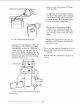
3. Hold the front carriage bearing with your
fingers as tight as possible and pull carriage
forward at the same time. If you can prevent
the bearing from turning an adjustment is re-
quired. (Figure 126)
Fig. 126 - Front Carriage Bearings
4. Repeat step 3 with the rear carriage bear-
ings.
To adjust the carriage bea_ngs perform the
following steps:
1. Clean and lubricate the bearing races and
the bead on which they ride prior to adjust-
ment.
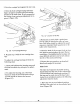
2. To adjust the bearing, use a 9/16 inch
wrench to hold the bolt head while using a
1/2 inch wrench to loosen the hex nut.
(Figure 127)
Fig. 127- Location of Flex Nut
3. Rotate the eccentric bolts a partial turn
(left or right) as required to take up loose-
ness. Both bolts should be adjusted an equal
amount to maintain blade squareness to the
table in the rip positions.
4. Hold the head of the eccentric bolts in their
new position and retighten the nuts. Do not
overtighten. Overtightening the bearings will
cause difficult operation and severly reduce
the life of the track and bearings.
5. Repeat the test procedure as described
above and readjust if necessary.
Miter Lock
The miter lock operates adjustable locking
bands which lock the arm to the column tube
in both indexed and unindexed positions. If
the arm can be easily moved by hand when
locked in an unindexed position the following
adjustment must be made.
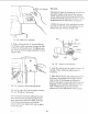
1. Move the arm to an unindexed position
and leave the miter lock in the unlocked posi-
tion. (Figure 128)
64