
Owner`s manual


3 Releasebevellockhandle,androtatethemotor
topositionthesawbladeendofshaftdown.Lock
bevelhandle,
4 Unlockand hold miter lockhandlein unindex
positionasshown,
Positionarmagainstleftstop(approximately50°
miter),Loosencarriagelockknobandposition
carriagedirectlyoverleft handchannel
NOTE:Forsafetyreasons,stopshavebeenprovided
to prevent360° rotationof theradialarm
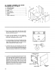
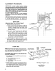
5. Slidethearborwrenchhandlebetweenendof
motor shaft and mounting channel to act as a
feeler gauge, Carefully lower the motor with
elevation hand wheel until the end of the motor
shaft is just touching the arbor wrench The
wrench should slide back and forth with only
slight resistance,, With 1/2" wrench tighten point
I_A _
NOTE: Do not change this elevation setting until
both teft and right hand table support channels have
been adjusted
6 Move arm and carriage to point "B", and tighten
support in the same manner,
7 Move arm and carriage to right hand support
channel, and level in the same manner you
adjusted the teft hand support channel
8 Recheck both support channels to make sure
that tightening screws did not affect the accuracy
of the adjustment,
9, Elevate saw and return motor to horizontal posi-
tion to provide clearance for installation of front
(work) table.
F
ARBOR WRENCH
POINT "*A"
ARBOR WRENCH
POINT -A"
TABLE MOUNTING
SUPPORT CHANNEL
(LEFT HAND)
Em'_
€,o ,==;
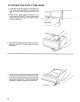
INSTALLATION OF FRONT (WORK)
TABLE
FRONT TABLE
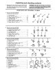
1 From loose parts bag #499, locate the following
hardware:
4 - Pan Head Bolts 1/4-20 x 1
5 - Flat Washers 17/64 x 5/8 x !/32
4 - Lockwashers 1/4
4 - Hex Nuts If4-20
From loose parts bag #529, locate the following
hardware:
t - Tee Nut 1/4-20
1 - Cup Point Set Screw 1/4-20 x 7/8
1 - U-Clip 1/4-20
1 - Pan Head Machine Screw 1/4-20 x I-3/4
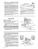
2 Place front table board upside down on a work-
bench or on the floor. Use a hammer to drive the
T-nut into the proper hole shown in illustration
Slide U-clip over proper hole in center flange of
base as illustrated,
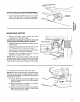
3. Place table on base with counterbored holes
facing up, Align the counterbored holes with
matching holes in support channels, lnstall the
five (5) 17/64 inch flat washers, and four (4) 1/4-
20 x 1 inch pan-head bolts, Just barely start the
cup point set screw and the one (1) 1/4-20 x !-3/4
inch pan head machine screw in table center
holes,
IJ-CLIP
1/4-20 x %3/4
PAN HD SCREW
1/4-20 X 1
PAN HD SCREW
19