
Owner`s manual
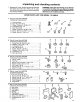


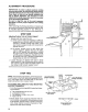


4. Installone (1) 1/4 Iockwasherandhex nut on
each of the four' (4) screwsin the support
channels,andtightenusingphillipsscrewdriver
and7/16wrenchor'socket.
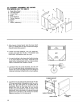
5. Laythereartableboardonedgeacrossthefront
tableto serveasastraightedge_Sightunderthis
straightedgeto determinewhetherthe front
tableboardishighorlowatitscenter.Alsocheck
to seeif tableiscontactingtheplastictrimcaps
installedper page16.If contactis occurring,
raisechannelsandreadjustpersteptwo.,
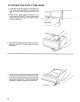
6. Ifthefronttableishighatcenter,firsttightenthe
holddownscrewwith phillipsscrewdriveruntil
thetableis level- thenusinga 1/8inchhex"L"
wrenchtightenthelevelingscrew.
If thefronttableislowatcenter,firsttightenthe
levelingscrew unti! the table is level- then
tightentheholddownscrew°
tf tableisnothighor low,tightenlevelingscrew
and centerholddownscrewsnug.Be sureto
tightenbothscrewswithoutmovingthecenter'of
thefronttable..
7..Recheckflatnessof front table to makesure
adjustmentdidnotchangewhentighteningfinal
screw..
STEP THREE
Squaring Crosscut Travel
NOTE: This adjustment helps ensure the blade
accurately travels square to the rip fence,
1, Index arm at 0° miter and lock,,
2 Install saw blade as shown.. Motor shaft has left
handed threads - turn nut counterclockwise to
tighten_
CAUTION: Do not overtighten arbor nut. Use arbor
wrench to "snug" nut in place. Overtightening could
distort the blade collars and cause blade to wobble.
3. Lower arm until saw blade just clears the front
table. Be sure the miter lock handle and the bevel
lock handle are locked.
SH
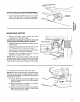
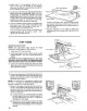
4.. Place a framing square on the table as shown and
position the blade and square until the leg of the
square just contacts a tooth of the blade. Mark
this tooth with a pencil,
NOTE: The framing (or combination) square must
be "true" - see chart of "Assembly and Alignment"
section on page 9 for checking method.
5, When the carriage is moved back and forth on
the arm, the marked tooth should just touch the
square at all points.. If marked tooth moves into
square or away from square the following adjust-
ments are required,
(a) Loosen the four (4) 1/4-20 socket set screws
on both sides of the front column support (2
on each side) with a 1/8" Hex "L" wrench as
illustrated on next page
(b) Move the arm in the proper direction to make
marked tooth follow edge of square when the
saw blade is moved along arm in a "crosscut"
manner'.
BEVEL LOCK
HANDLE
MARKED
TOOTH
MITER LOCK
HANDLE
2O