
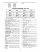
Specifications
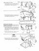
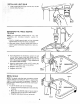
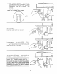

INSTALLING THE TABLE
SUPPORT
LOCK
t. Loosen support lock and raise table support by
turning table crank cRockwise until support is at a
working height level. Tighten support lock.
TABLE
SUPPORT
TABLE
RACK
TABLE
SUPPORT
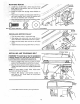
Remove protective covering from table and dis-
card. Place table in table support and tighten table
lock (located under table) by hand.
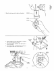
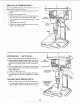
mNSTALLING THE HEAD
[ CAUT'ON: The head assembly weighs about 551
pounds, Carelully lift head.
1. Remove protective bag from head assembly and
discard. Carefully lift head above column tube and
slide it onto column making sure head slides down
over column as far as possible, Align head with
table and base.
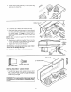
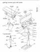
2. Locate (2) two lOmm dia. x 12ram long set
screws (see illustration) in loose parts bag.
TABLE t
LOCK TABLE
.i_; _ f
lOmm DIA. X 12mm "
SET SCREW
HEAD
LOCK
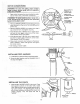
3. Install a set screw in each hole (as indicated) on
the right side of the head, and using a 5mm hex
"L" wrench, tighten the two head lock set screws.
11