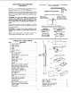
SAVE THIS MANUAL FOR FUTURE REFERENCE MODEL NO. 113.213853 DRILL PRESS WiTH 1/2 HP MOTOR Serial Number ® Model and serial number may be found at the rear of the head. You should record both model and serial number in a safe place for future use. MOTORIZED 15 INCH FLOOR MODEL DRILL • assembly • operating e repair parts CAUTION: Read GENERAL and ADDITIONAL SAFETY INSTRUCTIONS carefully Sold PART NO. SP4964 by SEARS, PRESS ROEBUCK AND CO., Chicago, IL. 60684 U.S.A. PRINTED IN USA.
FULL ONE YEAR WARRANTY OhL CRAFTSMAN DRILL PRESS If within one year from the date of purchase, this Cra_sman Drill Press fails due to a defect in material or workmanship, Sears will repair it, free of charge. WARRANTY SERVICE IS AVAILABLE BY SIMPLy CONTACTING THE NEAREST SEARS SERVICE CENTER/DEPARTMENT THROUGHOUT THE UNITED STATES. THIS WARRANTY APPLIES ONLY WHILE THIS PRODUCT This warranty gives you specific legal rights, vary from state to state. and SEARS, ROEBUCK AND CO., Dept.
21. DiRECTiON OF FEED 22. Feed work into a blade or cutter against the direction of rotation of the blade or cutter only. additional safety instructions for drill presses c. To avoid injury from parts thrown by the spring, follow instructions exactly as given and shown in adjusting spring tension of quilt. d.
add it....... mona!safety mnstrucuons Tot ar il"! presses c. Do not install or use any drill that exceeds 7" in length or extends 6" below the chuck jaws. They can suddenly bend outward or break, 13, Think Safety. Safety is a combination of operator common sense and alertness at all times when the drill press is being used. d. Do not usewire wheels, router bits. shaper cutters, circle (fly) cutters or rotary planers on this drill press.
UNPACKING AND CHECKaNG CONTENTS TOOLS NEEDED Model No. 113.213853 is shipped complete in one carton and includes a 1/2 HP 1725 RPM motor. COMBiNAT_ Separate all parts from packing materials and check each one with the "Table of Loose Parts" to make certain all items are accounted for, before discarding any packing material. WARNING: missing, do plug in the the missing rectly. COMBINATION DRAW MEDIUM SCREWDRIVER Apply a coat of paste wax to the table to prevent rust.
" " r equirements motor specifications and emectrmcaa MOTOR SPECIFICATIONS This power tool Is equipped with a 3-conductor cord This drill press is designed to use a 1725 RPM motor only. Do not use any motor that runs faster than 1725 RPM. It is wired for operation on 110-120 volts, 60 Hz. alternating current, and grounding type plug which has a grounding prong, approved by Underwriters' Laboratories and the Canadian Standards Association.
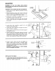
assembly WARNING: For your own safety, never connect plug to power source outlet until all assembly steps are completed. COLUMN I s ASSEMBLY OF COLUMN AND TABLE HARDWARE 1. Position base on floor. Remove protective covering and discard. 2. Remove protective sleeve from column tube and discard. Place column assembly on base, and align holes in column support with holes in base. 3. Locate four (4) 3/8-16xl 1/2 bolts and four (4) 3/8 Iockwashers among loose parts bag. 4.
assembly TABLE LOCK 2. Remove protective covering from table and discard. Place table in table support and tighten table lock (located under table) by hand. / TABLE TABLE SUPPORT iNSTALLING / THE HEAD CAUTION: The head assembly pounds. Carefully lift head. weighs about 55 HEAD 1. Remove protective bag from head assembly and discard. Carefully lift head above column tube and slide it onto column into position. Align head with table and base. HEAD LOCKS 2. Locate two (2)3/8-16xl/2 parts bag.
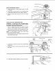
MOTOR PULLEY INSTALLING MOTOR PULLEY SET SCREW ___ 1. Loosen set screw in motor pulley using 1/8" HEX "L" wrench, FLAT SURFACE 2, Slide pulley onto motor shaft. Line up the flat surface on the motor shaft with the set screw in pulley. 3. Make sure the pulley does not rest on the lower guard. iNSTALLiNG AND TENSIONING LEVER SHAFT BELT WARNING: To avoid injury due to accidental starting always turn Drill Press off and remove switch key before making belt adjustments.
assembly 7. Locate center pul ey and place in proper hole. SPINDLE PULLEY IDLER PULLEY 8, Locate two (2) V-belts and choose speed for drilling operation. Install belts in correct position for desired speed. The shorter of the two belts is always positioned between spindle pulley and idler pulley. NOTE: Refer to chart on side on Drill Press for Recommended Drilling Speeds. \ \ 9.
MOTOR CONNECTIONS WARNING: For your own safety, never connect plug to power source outlet until all assembly steps are completed. _ LACK WIRE TERMINAL 1. Open motor connector box cover located on underside of motor using a flat blade screwdriver. COPPER GREEN / WARNING: To avoid electrocution, never connect anything but the ground wire (colored green) to the green screw. POST WIRE TO GREEN SCREW I . STRAIN RELIEF \ \\\\ \v- _ 2.
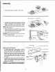
assembly 1. Clean out the TAPERED HOLE in the chuck; clean the spindle nose with a clean cloth. Make sure there are no foreign particles sticking to the surfaces. The slightest piece of dirt on the spindle nose or in the chuck will prevent the chuck from seating properly, This will cause the drill to "wobble." \\ 2. Apply a light film of oil such as Sears household oil to the spindle nose. 3. Place the chuck on the spindle nose and screw the locking collar up as far as it will go.
INSTALLING LIGHT BULB 1. Install a light bulb (not larger than 60 watt) into the socket inside the head. ADJUSTING THE TABLE SQUARE TO HEAD NOTE: The combination square must be "true". See "Unpacking and Checking Contents" section for method. . Insert a precision ground steel rod approximately 3" long into chuck and tighten. 2. With table raised to working height and locked on column, place combination square flat on table beside rod. , .
getting to know your drill press 24 27 FEED SPRING ADJUSTMENT 26 3 FEED BELT TE N SION LOCK SPRI NG DEPTH DRILL "ON-OFF" SWITCH SCALE 1 23 \ BELT GUARD DEPTH POINTER LIGHT "ON-OFF" SWITCH 2 BELT TENSION HANDLE 22 STOP 3 21 iLT TENSION LOCK HANDLE FEED STOP ROD 20 4 CHUCK LOCKING COLLAR 25 HEAD LOCK 5 19 SPRING CAP COLUMN CHUC 18 FEED HANDLE COLLAR 6 RACK 15 TABLE BEVEL 17 TABLE 16 7 SUPPORT 8 TABLE LOCK LOCK TABLE 14 ARM 13 Ilil I COLUMN QUILL AND SPINDLE ASSEMBLY
This Drill Press has 12 speeds as listed below: 300 375 525 560 700 860 RPM RPM RPM RPM RPM RPM 1450 1530 2000 2200 3400 4600 SPINDLE RPM RPM RPM RPM RPM RPM _._ 300 SPEEDS iN R.P, Mo -- 5zs sac 375 700 860 2000 2200 1450 1530 4600 ® ® See right side of Head for specific placement of belts on pulleys. 1. BELT GUARD ASSEMBLY . . . Covers pulleys and belt during operation of drill press. 2. BELT TENSION HANDLE...
geffing to know your drill press 26. DRILL "'ON-OFF" SWITCH... Has locking feature. THIS FEATURE IS INTENDED TO HELP PREVENT UNAUTHORIZED AND "POSSIBLE HAZARDOUS USE BY CHILDREN AND OTHERS. @ Insert KEY into switch. KEY NOTE: Key is made of yellow plastic. JI II IL_-__ r" i To turn drill ON.. Insert finger under switch lever and pull, To turn drill OFF... Push lever in. In an emergency;., the drill bit BINDS.., STALLS •.. STOPS .. or tends to tear the workpiece loose •.
CHUCKKEY... DRiLLiNG SPEED... Can be changed by placing the belt in any of the STEPS (grooves) in the pulleys. See Spindle Speed chart on right side of Head. It is a self-ejecting chuck key which will "pop" out of the chuck when you let go of it. This action is designed to help prevent throwing of the chuck key from the chuck when power is turned "ON". Do not use any other key as a substitute, order a new one if damaged or lost.
" n basic driJmpress operatmo Follow the following instructions for operating your drill press to get the best results and to minimize the I kelihood pf personal injury. -- Never perform any operation "FREEHAND" (hand-holding workpiece rather than supporting it on the table), except when polishing. Securely lock Head and Support to Column, Table Arm to support, and Table to Table Arm before operating drill press. Never move the Head or Table while the tool is running.
2 POSITIONING TABLE AND WORKPIECE Lock the table to the column in a position so that the tip of the drill is just a little above the top of the workpiece. Always place a piece of BACK-UP MATERIAL (wood, plywood...) on the table underneath the workpiece. This will prevent "splintering" or making a heavy burr on the underside on the workpiece as the drill breaks through. To keep the backup material from spinning out of control, it must contact the left side of the column, as illustrated.
basic drill press operation WARNING: TO avoid injury from spinning work or tool breakage, always clamp workpiece and backup material securely to table before operating Drill Press with the table tilted. Before turning the switch ON, bring the drill down to the workpiece lining it up with the hole location. To return table to original position: Ioosen set screw and bevet lock, tilt table back to 0 ° on bevel scale, and retighten set screw - then tighten bevel lock.
maintenance WARNING: For your own safety, turn switch "OFF" and remove plug from power source outlet before maintaining or lubricating your drill press. Frequently blow out any dust that may accumulate inside the motor. A coat of automobile-type wax applied to the table and column will help to keep the surfaces clean. WARNING: To avoid shock or fire hazard, if the power cord is worn or cut, or damaged in any way, have it replaced irnmediately.
trouble shooting WARNING: For your Own safety, turn switch "OFF" and always remove plug from power source outlet before trouble shooting. O CONSULT YOUR LOCAL SEARS SERVICE CENTER IF FOR ANY REASON MOTOR WILL NOT RUN. I TROUBLE PROBABLE Noisy Operation Drill Burns. Drill leads off... hole not round. CAUSE REMEDY 1. Incorrect belt tension. 1. Adjust tension, Seesection "ASSEMBLY- TENSIONING 2. Dry Spindle. 2. Lubricate spindle. See "Lubrication" section. 3. Loose spindle pulley. 3.
repair parts PARTS LiST FOR CRAFTSMAN 15" DRILL PRESS MODEL NO. 113.213853 2 24 _ _25 ( 3 110 FIGURE 1 Key No. Part No. 1 2 3 4 5 6 7 8 9 10 11 12 13 71385 71320 STD 502503 71392 71365 71314 STD 551137 STD 523715 71243 71259 STD 741006 71327 71378 Description Tube, Column Collar, Rack *Screw, Soc. Set 1/4-20x3/8 Handle Asm. Table Support Rack Base *Lockwasher 3/8 *Bolt, Hex Hd. 3/8-16xl 1/2 Bolt, Handle Handle, Sleeve *Nut Hex M6X1 Crank Support, Table 23 Key No. Part No.
repair parts _i_'_i_i! PARTS LiST FOR CRAFTSMAN 15" DRILL PRESS MODEL NO. 113.213853 45 44 46 42 SEE FIq • Any attempt to repair this motor may create a HAZARD unless repair is done by a qualified service technician. Repair service is available at your nearest Sears Store.
PARTS LiST FOR CRAFTSMAN 15" DRILL PRESS MODEL NO. 113.213853 FIGURE 2 ALWAYS ORDER BY PART NO. - NOT BY KEY NO. Key No. 1 2 3 4 5 6 7 8 9 !0 11 12 13 14 15 16 17 18 19 20 21 22 23 24 25 26 27 28 29 30 Part No. Description *Belt "V" 3/8x24 Ring, Retaining Ring, Retaining *Bearing, Ball 15MM Pulley, Center Pulley, Motor *Screw, Soc. Set 1/4-20x3/8 *Belt "V" 3/8x27 Pivot Asm. Screw, Pan Hd.
PARTS LIST FOR CRA_SMAN 15"DRILL PRESS MODEL NO. 113.213853 "! 6 14 FIGURE 4 Key No. Pad No. Description 1 2 3 4 5 6 7 8 9 10 11 12 13 14 15 60509 STD 315235 71384 60503 STD 315255 71374 71318 STD 541150 STD 522512 71321 STD 541025 71331 STD 541350 71366 71263 Ring, Retaining 21/32 *Bearing, Ball 17MM Tube, Quill Bearing, Thrust *Bearing, Ball 25MM Spindle Chuck *Nut, Hex 1/2-20 *Screw, Hex Hd.
NOTES: 27
MOTORIZED 15 INCH FLOOR MODEL DRILL PRESS SERVICE Now that you have purchased your 15 inch drill press should a need ever exist for repair parts or service, simply contact any Sears Service Center and most Sears, Roebuck and Co. stores. Be sure to provide all pertinent facts when you call or visit. The model number of your 15 inch drill press will be found on a plate attached to the rear of the head. MODEL NO. 113.