
Owner`s manual


assembly
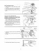
7. Locate center pul ey and place in proper hole.
SPINDLE PULLEY IDLER PULLEY
8, Locate two (2) V-belts and choose speed for drilling
operation. Install belts in correct position for desired
speed. The shorter of the two belts is always
positioned between spindle pulley and idler pulley.
NOTE: Refer to chart on side on Drill Press for Recom-
mended Drilling Speeds.
9. Apply tension to belt by turning Belt Tension Handle
counter clockwise until belt deflects approximately
1/2 inch by thumb pressure at its center.
10, Tighten Belt Tension Lock Handles.
CAUTION: Over tensioning belt may cause motor not
to start or damage bearings,
11. If belt slips while drilling, readjust belt tension,
\
\
BELT
TENSION
HANDLE
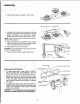
INSTALLING UPPER GUARD
1. To attach upper guard, locate three (3) 8-32xl/2
pan hd, screws, three (3) Iockwashers - ext. #8,
and three (3) 8-32 hex nuts among loose parts bag.
2_
Install the three pan hd. screws through the three
holes in the upper guard and into the hinge located
on the belt guard. Install Iockwasher and nut on
each screw and tighten with screwdriver or adjusta-
ble wrench.
3. To attach upper guard knob, locate knob and 1/4-
20x3/8 pan hd. screw among loose parts bag. Install
screw in hole located in upper guard and attach
knob turning until tight,
WARNING: To avoid possible injury keep guard in
place and in proper working order while operating.
NUT HEX 8-32
_ UPPER GUARD KNOB
UPPER GUARD
PAN HD. SCREW
1/4-20X3/8
10