
Owner`s manual

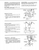

MOTOR CONNECTIONS
WARNING: For your own safety, never connect
plug to power source outlet until all assembly steps
are completed.
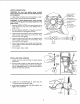
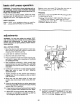
1. Open motor connector box cover located on under-
side of motor using a flat blade screwdriver.
WARNING: To avoid electrocution, never connect
anything but the ground wire (colored green) to the
green screw.
2. Remove GREEN SCREW and insert through round
metal terminal on the end of the GREEN wire of
power cord.
3. Reinsert GREEN SCREW in threaded hole that it
was removed from and tighten securely.
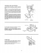
4. Insert terminal end of WHITE wire on spade terminal
(next to silver post) marked #4 on the motor. Push
terminal firmly until seated.
5. Inset terminal end of BLACK wire on spade terminal
(next to copper post) marked #1 on the motor. Push
terminal firmly until seated.
6. Close motor connector box being sure that power
cord is seated in strain relief groove and tighten box
cover screws.
7. Do not plug in power cable.
_ LACK WIRE TO
TERMINAL #1
COPPER POST
GREEN WIRE
/ TOGREENSCREW
I . STRAINRELIEF
\ \\\\ \v- _ II ""_'l_"_--_ WHITEWIRE
MOTOR
GREEN
(GROUND)
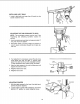
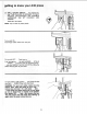
iNSTALLiNG FEED HANDLES
t. Locate three (3) rods and three (3) knobs among
loose parts.
2. Screw a knob on each rod,then screw the other rod
end intothe threaded holes in the hub and tighten.
Use an adjustable wrench on the flats provided to
tighten the feed rods securely.
FLAT:
FEED
FEED
KNOB
HUB
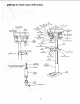
3. Locate one (1) 10-32x3/8 pan hd. screw and one
(1) pointer among loose parts bag.
4. Install screw through pointer into table support, and
tighten with screwdriver.
o
POINTER
SCREW
11