
Operating instructions

c. TO lockswitchin OFFposition..,holdswitchIN
withonehand.,. REMOVE key with other hand,
ALWAYS LOCK THE SWITCH "OFF" WHEN
SHAPER IS NOT IN USE... REMOVE KEY AND
KEEP IT IN A SAFE PLACE,,. ALSO... tN THE
EVENT OF A POWER FAILURE (ALL OF YOUR
LIGHTS GO OUT) TURN SWITCH OFF .,, LOCK IT
AND REMOVE THE KEY. THIS WILL PREVENT
THE SHAPER FROM STARTING UP AGAIN WHEN
THE POWER COMES BACK ON,
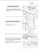
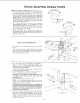
2, ELEVATING CONTROL LEVER
The Elevating Control Lever moves the spindle
vertically a distance of 7/8-inch to locate the cutter at
the desired vertical position.
3. SPINDLE LOCK KNOB - used to lock the spindle and
quill assembly after the desired height has been
determined.
CAUTION: Always release the quill lock knob before
attempting to change the position of spindle and
tighten the knob securely before starting operation.
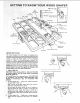
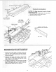
4. SPINDLE - This shaper is designed for use with
maximum 2-1/2-inch diameter cutters having a 1/2-inch
diameter bore.
5. SPACERS - A total of three spacers are provided, two
7/16 inch thick and one 1/4 inch think for positioning
the cutter for desired shapes.
6. KEYED WASHER - Must always be positioned
immediately below the spindle nut.
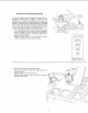
7. FENCE ADJUSTING KNOB - Each fence face may be
moved forward or backward by turning the fence
adjusting knobs.
8. FENCE LOCK KNOB - After the desired fence face
position has been selected, the fence is secured by
tightening the fence lock knobs.
9. FENCE FACES - Each fence may be moved forward
or backward by releasing the fence lock knob and
turning the fence adjusting knobs. Each fence face
operates independently of the other, by means of the
adjusting mechanism. After the desired fence position
has been selected, it is secured by tightening the fence
lock knob. The fence faces wilt close in from a
maximum three-inch opening down to one-inch for
small diameter cutters, by loosening the two screws in
the front of each face and sliding the face to the desired
posiiton. The screws must be tightened securely after
each setting.
CAUTION: The opening between inner ends of fence faces
should never be larger than required to just clear the
particular cutter being used. ALWAYS ROTATE THE
SPINDLE BY HAND BEFORE STARTING THE SHAPER
MOTOR TO MAKE SURE CUTTER DOES NOT STRIKE
FENCE FACES.
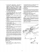
10. CUTTER GUARD
NOTE: Used for curved or irregular shaping only-
fence must be removed and starting pin must be in
place on in-feed side.
11.
12.
Provides added protection for irregular shaping. Guard
is adjustable for various thickness of material.
CAUTION: Always rotate the spindle by hand before
starting the shaper motor to make sure cutter does not
strike guard.
STARTING PIN
The Starting Pin must be used as a pivot to support the
work until it has been fed into the cutter and against
the collar. The Starting Pin may be located in either of
the two threaded holes near the table insert opening,
depending upon the direction of rotation, but
ALWAYS on the in-feed side.
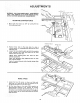
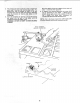
REMOVING AND INSTALLING CUTTERS
a. Raise spindle to maximum height
b. To REMOVE cutter, hold spindle with the t/4" hex
wrench and loosen nut with wrench provided as
shown -- Reverse procedure to TIGHTEN SPINDLE
NUT.
NOTE: TO AVOID POSSIBLE BENDING OF THE
SPINDLE LOOSEN OR TIGHTEN NUT WITH BOTH
WRENCHES POINTING AS NEARLY tN THE SAME
DIRECTION AS POSSIBLE.
CAUTION: Always have the keyed washer directly
under the nut, otherwise the nut may loosen and
serious injury could result.
1/'4 IN, HEX WRENCH
\
LOOSE N
/
t/
TI GHTE N
WRONG
R_GHT ,!,,
13