
Operating instructions


ADJUSTING RiP SCALE POINTER
1. Turn ELEVATION HANDWHEEL clockwise untH
blade is up as high as it will go,
IMPORTANT: BLADE must be SQUARE (90 ° ) to
TABLE. in order to ALIGN rip fence.
2. Position fenceon right side of sawblade so that it
touches the sides of the teeth.., tighten lock
handle.
3. Loosen screw holding the pointer . . . adjust
pointer so that it points to "0" .. tighten screw.
NOTE: If you cannot adjust pointer so that it
points to "0", loose n the screws holding the fro nt
guide bar and move the guide bar.
POINTER
_-K HANDLE
INSTALLING BLADE GUARD
1_ From among the loose parts, find:
2 Hex Head Screws, 1/4-20 x 5/8 in. long
3 Hex Head Screws, 5/16-18 x 5/8 in. long
2 Hex Head Screws, 5/16-18 x 1 in. long
2 Hex Nuts, 1/4-20 (approx. dia. of hole 1/4 in.)
2 Lockwashers, 1/4 in. External Type
(approx. dia. of hole 1/4 in.)
2 Lockwashers, 5/16 in. External Type
(approx. dia. of hole 5/16 in.)
1 Thumbscrew
Blade Guard Support
Spreader Support
Spreader Rod
2. Before installing the blade guard, you mustcheck the
heelingadjustment (parallelism of sawblade to miter
gauge groove). The procedure for making this check
and adjusting it are found inthe "Adjustments" sect ion
of this manual. Refer to "Heeling Adjustment or
Parallelism ol Saw Blade to Miter Gauge Groove".
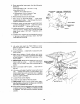
BLADE GUARD _,_ ''-_
SUPPORT 5/16-18
\
HEX HD.
5/16ol 8 X: \
HEX HD.
SCREW
5/16 IN.
LOCKWASHERS
5/16-18 X 5/8 IN
HEX HD. SCREWS
3. Lower the blade.
4. Screw the MOTOR BASE CLAMP SCREWS part
way into cradle. Screw the 5t16-18 x 5/8 inch Hex
Head screw into the blade guard support.
5. Attach BLADE GUARD SUPPORT... DO NOT
TIGHTEN SCREWS,
r
THUMB SCR EW//__
6 Insert SPREADER ROD intoSPREADER SUPPORT SPREADER
ti;thleP_nitlitsint° n°tch" Insert THUMBSCREW and sFRLFATcE
SPREADER
(INTO SUPPORT), SUPPORT
,,