
Owner`s manual


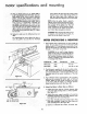


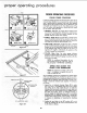

b. Adiusting the Miter Gauge.
(1) Loosen the lock handle, disengage stop pin, hold
the square soLid{_ against the rod assembty a*._d
face and tighten lhe Jack handle firmly by hand
Always tighten the tack handle hand fight o_ly.
Do not use a wrench or pJiers_
(2) Recheck to make sure that tightening the iock
handle did not alter the setting. Remove the
square from the gauge.
(3)
Loosen the two screws that attach the indicator
block to the rod assembly. Shift the indicator
block until the stop can be pushed solidly into
its detent. Hold the indicator btock aligned with
the rod assemb{_/and the stop pin seated firmly
in the detent and tighten the two screws.
(4) Loosen the lack handle and recheck for accuracy
with the combination square. (Make certain the
stop pin is fully seated.) Tighten the Jack handle
and readjust if necessary.
(5) After completing the above adiustment, _oasen
the pointer attaching screw, set pointer at "0"
(zero) and tighten the screw.
NOTE: Detents at the two 45-degree positions
are jig bored. When the gauge is adjusted
for 90-degree cut, the 45_degree positions
are col'root.
(6) Remove the miter gouge from saw tabJe until
remaining checks have been completed.
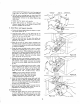
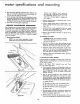
13. lnstaq! Saw Guard Assembly as Follows:
a. Installing Splitter BJede Bracket.
(1) Install the two 5/16-18xSi8-inch, hex-head
screws laosemy in holes at rear of saw cradle as
these screws cannot be installed after attaching
the splitter blade bracket_ (See figure 340 These
are the screws thai secure the motor support in
the cradle.
(2) tnstaH the splitter b;ade bracket with two 5/16-
18xl inch box-head screws. Tighten screws
finger tight at this time.
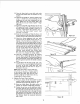
(3) Refer to figure 35 and hold the splitter rod to
the left of splitter support_ Rotate the splitterrod
so the "flat" on the rodis toward the operator.
Then slide the spJiffer rod into the spfitter sup-
port from the left until the pin (through the rod)
bottoms in the slots in splitter support. (See figure
35.) Tighten the thumb screw firmly against the
"'flat'" af splitter rod.
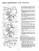
(4) Slide the splitter rod (attached to splitter sup-
port) into the sp{iii'er blade bracket until the
splitter blade is directly behind the saw blade.
(See figure 36.) Do not be concerned if the split-
ter bar does nat align with saw blade vertically
as this will be Corrected in the next step. "lFighten
the socket-head set screw in splitter blade bracket
with a 5/32-inch he×-L wrench.
C'EWHE* L t
5/,6 {1J
Figure 34 ""
PIN
\
TER SUPP©RI
\
13