Save This Manual For Future Reference ISears owners manual * MODEL NO. 113.298142 SAW ON LY 113,298032 SAW WITH LEGS TWO TABLE EXTENSIONS AND MOTOR 113.298240 SAW WITH LEGS TWO TABLE EXTEN SIONS MOTOR AND HOLD DOWN Serial Number _ _ Model and seria number may be found at the left-hand side of the base. You should record both model and serial number in a safe place for future use. 10-INCH TABLE SAW CAUTION: • assembly Read GENERAL and ADDITIONAL SAFETY .
FULL ONE YEAR WARRANTY If withirl-one year workmanship, States. Sears from the will date repair of purchase, this it, free of charge.
ADDITIONAL WARNING: FOR OPERATE YOUR ASSEMBLED AND INSTRUCTIONS... AND UNDERSTAND 1. SAFETY YOUR OWN SAFETY, DO NOT SAW UNTIL IT IS COMPLETELY INSTALLED ACCORDING TO THE AND UNTIL YOU HAVE READ THE FOLLOWING. 2. GENERAL TOOLS... GETTING 3. 4. 5. 6. BASIC SAW OPERATION . . . SEE PAGE ADJUSTMENTS . . . SEE PAGE 29 MAINTENANCE... SEE PAGE 34 STABILITY OF SAW If there INSTRUCTIONS SAFETY INSTRUCTIONS SEE PAGE 2 TO KNOW YOUR SAW ...
R. DONOTremove smallpieces of cutoff material that maybecome trappedinsidethe bladeguard whilethesawisrunning. Thiscouldendanger your handsor cause a kickback. Turnsaw"OFF"and waituntilbladestops. S. Useextracarewhenripping woodthathasatwisted grainor istwistedor bowed- it mayrockonthe tableand/orpinchthesawblade. 10.KNOW YOURCUTTING TOOLS A Dull,gummy, or improperly sharpened orset cutting B. tools can cause material to stick, jam, sta!l the saw, or kickback at the operator.
Plug power cord into 110-120V properly outlet protected by a 15-amp. time delay fuse or circuit breaker. IF YOU ARE PROPERLY QUALIFIED NOT SURE GROUNDED, ELECTRICIAN. WARNING: DO THE TERMINALS REMOVING THE THAT HAVE grounded type or Circuit-Saver LUG ADAPTER YOUR IT GROUNDING OUTLET CHECKED IS BY MAKE A 3-PRONG SURE THIS CONNECTED PLUG KNOWN NOT PERMIT FINGERS TO TOUCH OF PLUG WHEN INSTALLING OR PLUG TO OR FROM THE OUTLET.
UNPACKING AND CHECKING CONTENTS COMBINATION SQUARE NEEDED MUST BE TRUE. STRAIGHT EDGE OF BOARD 3,/4" DRAW LIGHT BOARD ALONG Medium Screwdriver Small Screwdriver LINE ON THICK. THIS EDGE MUST BE PERFECTLY STRAIGHT. THIE EDGE, <_'\x Phillips Type ___rewdriver Wrenches _,'+'Tr!;iiii_il I:III_,L.'III:II',III!I ii.11'i::]ii_ii' I Combination / 3/8 In. 7/16 in. 1/2 in. 9/16 In. 3/4 In. Square SHOULD BE NO GAP OR OVERLAP HERE WHEN SQUARE IS FLIPPED OVER Model carton 113.
ItemPart Name Z Z AA AA AA AB AC AD AE AF AG Qty. Hex Nut, 5/16-18 (approx.die. of hole 5/16 in.) ........... Hex Nut, 1/4-20 (approx.die. of hole1/4 in.) ............ Lockwasher,5/16 in. ExternalType (approx.die. of hole 5/18 in.) ........... Lockwasher,1/4 in. ExternalType (approx.die. of hole 1/4 in.) ............ LockwasherNo. 10 ExternalType (approx.dia. of hole3/16 in.) ........... CarriageBolt, 5/16-18 x 3/4 in. long ....... Rip FenceGuideBarSpacer .............. Wire Tie ..........................
ASSEMBLY Before mounting the saw on legs, a stand or a bench, the Table Insert and Blade Squareness must be checked at this time. LOC:KWASHER INSTALLING 1. HANDWHEE / LS Line up FLAT SPOTS on shaft and handwheel, push handwheel onto shaft. Install screw and Iockwasher to lock handwheel on shaft. ELEVATION HANDWHEEL CHECKING 2. TABLE INSERT Insert should be flush with table top. Check as shown. Loosen flat head screw tha_ holds insert and adjust the four set screws as necessary.
ASSEMBLING STEEL LEGS NOTE: Steel Legs are furnished and 113.298240. From among following Hardware: 24 Truss Head Screws, screw is rounded) 24 Lockwashers, hale 1/4 in.) 24 Hex Nuts, 8 Hex Nuts, 4 Leveling Assemble 1. 2. 1/4 - 20 x 5/8 in. long (top of (approx. dia. of SIDE STIFFENER 1/4 in. External 1/4 - 20 (approx. 1/2 - 13 (approx. Type dia. of hole dia. of hole I/4 in.) 1/2 in.) feet. the legs as shown ...
ATTACHING AND ASSEMBLING TABLE If you received Table them at this time. Extensions 1. loose From among hardware. the Support Stiffener with_ou,r parts find 4 4 Corner Corner 16 16 16 8 8 8 Truss Hd. Screws 1/4-20 x 1 Ext. Lockwashers 1/4 Hex Nut I/4-20 Hex Hd. Screws 5/16-18x 1-1/4 Ext. Lockwasher 5/16 Hex Nut5/16-18 Flat Washers (Dia. of hole 17/64) 8 Flat Washers (Dia.
Insertboltsthroughholesin front of saw table ... middle and on right side of install Iockwashers and nuts. DON'T SCREW NUTS ON them started on the screws. 6. 7. Remove the 3 screws from ALL THE rear of table WAY, just extension. Insert 1 in. long screws in SECOND and FOURTH of rear bar and attach to table the same way. Insert round ends of FENCE GUIDE holes at outer end of bars. BAR get ROD holes through NOTE: The ends of the ROD are not threaded ...
8 THICKNESSES OF PAPER 13, Raise blade all the way up, 14. Carefully move fence against 15. Move front approximately blade. bar until "'0"" mark inline with indicator. on rip scale is 16. Move FRONT bar upwards until fence is approximately 1/32 in. above table ... tighten screw at left end of bar. NOTE: Fold a piece of newspaper making 8 thicknesses and place between rip fence and table to act as a spacer. This will hold the fence off of the table approx. 1/32 in. 17.
For very close adjustments, grasp the guide bar with both hands and move the fence with your thumbs, Place fence on saw but DO NOT LOCK IT. Move the REAR END of the fence slightly to the right or left ... when you release it, the fence should "spring" back to its original position. If it does not, the spring 1. Loosen the screws. pressure 2. toward Move Spring slightly If the fence does not slide easily of the spring can be REDUCED. 1. Loosen 2. Move must be INCREASED. front of fence.
SCREWS The rip fence must be PARALLEL with (see page 31) ana miter Gauge grooves.. until it is along side of groove. Do NOT should be parallel to groove. If it is not; 3, Loosen B. Hold fence head tightly aga=nst bar . . move end of fence so that it is parallel with groove. C. Alternately 1. Turn "'Hex. FENCE HEAD A. ADJUSTING the two the sawblade Move fence LOCK IT. !t tighten Head Screws." the screws. RIP SCALE INDICATOR ELEVATION HANDWHEEL TABLE, in order to ALIGN clockwise \ unt
THUMB SCREW SPREADER 5o Insert until it. SPREADER pin fits into ROD notch. int0SPREADER Insert SUPPORT Thumbscrew X ROD \ and tighten FLAT SURFACE SPREADER SUPPORT SUPPORT) _, (INTO _, U 6. 7. Slide SPREADER ROD into left end of ROD extends GUARD SUPPORT approximately 1/4 until inch beyond edge of SUPPORT Screw in SUPPORT. .., Head Attach screws SPREADER to SPREADER up Hex SUPPORT are all the way back in the SLOTS •. • tighten 8. Snug 1/4-20 HEX HD. SCREW 1/4 IN.
SPACE EQUAL TOAPPROX. 3 THICKNESSES OF PAPER KERF WOOD 14,IMPORTANT:The SPREADER mustalwaysbe PARALLEL tothesawblade andintheMIDDLE ofthe cut(KERF)made bythesawblade. NOTE:Thespreader is thinnerthanthewidthof the KERFbyapproximately sixthicknesses of paper. BLADE / SPREADER SPACE EQUAL TO APPROX. 3 THICKNESSES OF PAPER LOOKING DOWN ON SAW 15. Make two folds in a small piece (6 x 6 in.) of ordinary NEWSPAPER making three thicknesses, The folded paper will be used as a "'spacing gauge".
5. Fromamongthe looseparts,find the following hardware: 4 Carriage Bolts,5/16-18x 3/4in.long 4 Hex.Nuts,5/16-18 (approx, dia.ofhole5/16in.) 4 Lockwashers, 5/16in,External Type (approx. dia.ofhole5/16in.) 6. Place motoronMOTOR BASE... insertboltsthrough holesin base... then throughthemotor.Install Iockwashers, andnuts. 7. Positionmotorso thatedgeof MOTORFOOTand MOTOR BASEareeven.,,slidemotorallthewayto theRIGHT,..tightenthefournuts. 8. Loosenset screwin motorpulleyusing5/32 in. setscrew wrench.
TWO HOLES CLOSEST TOGETHER INSTALLING 1. Remove 2. Screws furnished screw them into the belt and motor BRACKET. 3. Position BELT screws BELT GUARD then BELT / BELT GUARD SUPPORT BRACKET pulley. % with guard are "self threading" holes iN BELT GUARD SUPPO'R'T remove SCREW \ BELT GUARD SUPPORT them GUARD SUPPORT BRACKET and GUARD SUPPORT as shown and install ... make sure motor shaft is in CENTER the of BELT GUARD f hole in SUPPORT. \ PIVOT SCREW ! CENTERED OPENING Insta three CLIPS
8° Press guard approximately onto support so that bottom 3/4 in. away from beFt° of guard is NOTE: To remove guard, lift up on LONG TABS of clips ... pull guard outward. The clips should remain on the BELT GUARD SUPPORT. 8/4 i ASSEMBLING (Included with HOLD-DOWN Model 113.298240) Locate the clamp assembly, support and two washers in loose parts bag. Screw the support gauge head.
GETTING TO KNOW YOUR SAW 9 SAWBLADE 7 8 MITER GAUGE LOCK HANDLE 6 MITER |0 BLADE GUARD TABLE INSERT EXACT-I-CUT ANTIKICKBACK PAWLS _ GAUGE RIP FENCE RIP FENCE LOCK HANDLE 4 TILT LOCK HANDLE (UNDERNEATH TABLE) 2 ELEVATION HANDWHEEL 3 ] ON-OFF 1 TILT HANDWHEEL SWITCH ON-OFF SWITCH CAUTION: Before turning switch on, make sure the blade guard is correctly installed and operating properly. @ The On-Off Switch has a locking feature.
2 ELEVATION blade, Turn to lower. HANDWHEEL . . . elevates or lowers the clockwise to elevate ... counterclockwise TILT HANDWHEEL ... tilts the cutting. "_'urn clockwise to tilt counterclockwise to tilt toward right. blade toward If necessary, the miter gauge head can then slightly to compensate and then locked. Slots are provided in the miter gauge for attaching an AUXILIARY FACING to make it easier to cut long pieces.
9 REMOVING AND INSTALLING SAWBLADE. WARNING: FOR YOUR OWN SAFETY, TURN SWITCH "OFF" AND REMOVE PLUG FROM POWER SOURCE OUTLET BEFORE REMOVING OR INSTALLING SAWBLADE. A Raise Blade Guard...remove insert. B. To REMOVE blade, olace a block of wood against front of blade .. PULL arbor wrench toward you to LOOSEN arbor nut. BLADE GUARD BLADE C. To TIGHTEN against rear from you. Always tighten SHOWN GUARD NOT FOR SHOWN PICTURE CLARITY FOR side of the arbor ... make sure the teeth of the saw ...
BASIC SAW OPERATION WORK HELPERS Before "Basic Notice cutting any wood Saw Operations". that in order on to your make AUXI saw, some study of the all of the cuts, it NOTE: is which FENCE/WOR Since Fence, necessary to use certain devices "Work Helpers" like the Push Stick, the Push Block and the Auxiliary Fence/Work Support, LIARY K SUPPORT Make one using a piece of 3/8 in. and 3/4 Fasten together with glue and woodscrews. both the the Push 4-3/4 Block in, plywood.
CROSSCUTTING CROSSCUTTING the grain, at 90 °, side of the wood. is known as cutting wood across or square with both the edge and the flat This is done with miter gauge set at "'0". The graduations on the miter gauge provide accuracy for average woodworking. In some cases where extreme accuracy is required, when making angle cuts, for example, make a trial cut and then recheck it with an accurate square, or protractor. If necessary, the miter gauge head can be swiveled to compensate for any inacurracy.
1. NEVER USE" THE RIP FENCE AS A LENGTH S',v, BECAUSE THE CUTOFF PIECE COULD BIND BETWEEN THE FENCE AND THE BLADE CAUSING A KICKBACK. 2• When making repetitive cuts shorter than 6 in., clamp a block of wood 2 in. long to the table to act as a length stop. Do not clamp directly to the bottom edge of the table because the "swivel" of the clamp will not grip properly. Place a _mall block of wood between the bottom edge of the table and the "C" clamp.
USING THE HOLD-DOWN When cutting wide pieces of material, move the clamp assembly forward as far as it will go... grip the lock handle and tighten by turning clockwise until lock handle is secured. Tighten both wing screws. When cutting narrow pieces of material, adjust the clamp assembly with the clamp over the center of the workpiece. Grip the lock handle and tighten by turning clockwise until lock handle is secured. Tighten both wing screws, The clamp screw contains a "rapid approach" feature.
USING THE RIPPING, BEVEL RIPPING, PLOUGHING, MOLDING, RESAWING ANO RABBETING are performed using the RIP FENCE together with the AUXILIARY FENCE/WORK SUPPORT, PUSH STICK OR PUSH BLOCK. WARNING: FOR YOUR OWN SAFETY, ALWAYS OBSERVE THE FOLLOWING SAFETY PRECAUTIONS IN ADDITION "ro THE SAFETY INSTRUCTIONS ON PAGES 2, 3, and 4. Never make these cuts FREEHAND rip fence or auxiliary devices the blade could bind in KICKBACK.
When PUSH "WIDTH OF RIP" is 2 in. STICK to feed the work. to 6 in. wide USE THE When WIDTH OF RIP is NARROWER than 2 in,, the push stick CANNOT be used 10ecause the guard will interfere... USE the AUXILIARY FENCE/WORK SUPPORT ane PUSH BLOCK. Attach Auxiliary two "'C'" clam _s. Fence/Work Support to rip fence with \ Feed the workpiece by hand along the AUXILIARY FENCE until the end s approx. 1 n. oast the front edge of the table. Continue [o feed using the PUSH BLOCK.
PLOUGHING AND MOLDING MOLDING is shaping the workpiece with the grain the long way of the workpiece, using the fence. Use proper holddowns and feed devices, PLOUGHING is grooving with the grain the long way of the workpiece, using the fence. USE proper holddowns and feed devices. RESAWING RESAWlNG is known as ripping a piece of wood through its thickness. Do not attempt to resaw BOWED or WARPED material. NOTE: To RESAW a piece of wood wider than 3-3/8 in ....
DADOING Instructions for operating the Dado Head are contained booklet furnished with the Dado Head The Recommended Dado Head is Recommended Accessories in this manual. Th_ arbor on widest cut that listed the saw, is omy long enough can be mace is 13/16" wide. It is not necessary screwing on the arbor ALWAYS USE RECOMMENDED to install nut. the outside loose collar DADO INSERT ACCESSORIES. TABLE DADO NSERT / under so that Make sure the arbor SAW iP the before nut is tight.
ADJUSTMENTS LOCK KNOB WARNING: FOR YOUR OWN SAFETY, TURN SWITCH "OFF" AND REMOVE PLUG FROM POWER SOURCE OUTLET BEFORE MAKING ANY ADJUSTMENTS. MITER "0" BAR GAUGE NOTE: The slots for the stop pin and the graduations are manufactured 1:o very close tolerances which provide accuracy for average woodworking. In some cases where extreme accuracy is required, when making angle cuts, for example, make a trial cut and then recheck it.
If tooth does not touch the same amount mechanism underneath must be adjusted blade PARALLEL to GROOVE. trunnion must the the FRONT Rear B. combination square if there is a space between marked tooth and end of square in step 4. Rear trunnion must be moved AWAY from the if position in the groove. marked tooth moved ... make A. square be to pushes TOWARD square REAR TRUNNION TRUNNION the out of REAR-TRUNNION SCREWS 7.
I 3. Operate the tilt lock handle (COUNTERCLOCKWISE) to loosen the tilt clamp screw. 4. NOTE: Handle is spring loaded for engagement with screw head -. must be pushed inward for disengagement whenever necessary to obtain a new grip on screw head. 5. "1 Rotate tilt handwheel CLOCKWISE a few turns to tilt blade. Now rotate handwheel COUNTERCLOCKWISE until it stops. Blade should now and pointer should point to "0". be square with table TILT I If blade is SQUARE A.
45 ° POSITI ON TILT blade to LEFT as far as it will go. It will stop when the PIVOT NUT is against the 45 ° STOP COLLAR. A. Place an ACCURATE square against blade. Make sure square is not touching the TIP of one of the saw TEETH. If blade is 45 ° to table: A. Check pointer. If POINTER scale; DOES NOT !_oint to the A. Remove B. Loosen two screws on scale and POINTER points to 45 ° mark. Elevation C. Install Elevation 45 ° mark on the Handwheel. adjust scale until Handwheel.
MAINTENANCE WARNING: FOR YOUR OWN SAFETY, TURN SWITCH "OFF" AND RIEMOVE PLUG FROM POWER SOURCE OUTLET BEFORE MAINTAINING OR LUBRICATING YOUR SAW. 2. Rotate pawl toward rear of above top of spreader. 3. Hold spreader of workbench. Do not allow sawdust to accumulate inside the saw. 4. Using teeth. Frequently blow. out any dust that may accumulate inside the saw cabinet and the motor.
TROUBLE WARNING: FOR YOUR OWN SAFETY, OUTLET BEFORE TROUBLESHOOTING. TURN SWITCH TROUBLE TROUBLE "OFF" AND SHOOTING PROBABLE Excessivevibration. SHOOTING ALWAYS REMOVE PLUG POWER -- GENERAL CAUSE REMEDY 1. Blade out of balance. 1. Discard Blade and use a different 2. Damaged 2. Replace as Indicated. V-Belt FROM Pulleys blade. or poor belt. Cannot make square I. Miter Cut when crosscutting. Cut binds, burns or stalls motor gauge not adjusted 1.
TROUBLE TROUBLE SHOOTING PROBABLE -- MOTOR (Continued) REMEDY CAUSE Motor starts sh)wly or fails to com_.=up 1. Low voltage will not trip relay. 1. Request voltage check from the power company. to full speed. 2. Windings burned out 2. Have motor repaired or replaced. Motor overhea,ts. or open. 3. Starting relay not 3. Have relay replaced. operating. 1. Motor overloaded. 1. Feed work slower into blade. 2. Clean out sawdust to provide normal air 2. Improper cooling.
PARTS LIST FOR CRAFTSMAN 10 INCH TABLE SAW MODEL NO. 113.298142, 113.29_032 & 113.
PARTS LIST FOR CRAFTSMAN 10 INCH TABLE SAW MODEL NO. 113.298142, 113.298032 & 113.298240 Always order by Part Number - not by Key Number. FIGURE Key No. 1 2 3 4 5 6 7 8 9 10 11 12 _O 13 14 15 16 17 18 Part No. 62579 STD522506 STD 551225 STD 541025 STD 523110 62541 STD 551231 STD 541031 60388 62703 62718 STD 501102 133645 62748 62493 62773 62710 62709 Assembly *Screw, Hex Hd. * Lockwasher, *Nut, STD 523107 STD 551031 62539 60381 STD 523117 62704 24 (See Fig.
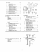
PARTS LIST FOR CRAFTSMAN 10 INCH TABLE SAW MODEL NO. 113.298142, 113.298032 & 113.298240 1 2 3 18 I 19 20 I 21 16 15 1 61-'-_LL=_ 25 \ 22 39 44 38 43 37 36 35 34 34 31 33 32 Figure 2
PARTS LIST FOR CRAFTSMAN 10 INCH TABLE SAW MODEL NO. 113.298142, 113.298032 & 113.298240 FIGURE Key No. 1 2 3 4 5 6 7 8 9 10 11 12 13 14 15 16 17 18 19 20 21 22 23 24 25 26 27 28 29 30 31 32 33 Part No. 62292 STD 541O31 STD 532507 60206 60205 STD 551037 63011 62295 30426 62696 60175 62498 6362 3540 62437 62698 37900 STD 523710 STD 551237 Support, Screw, *Pin, Spreader Thumb 5/!6-18 Roll 3/16 x 1-1/4 *Screw, x 1 Hex Hd. 5/16-18 *Screw, Hex Hd.
PARTS LIST FOR CRAFTSMAN 10 INCH TABLE SAW MODEL NO. 113.298142, 113.298032 & 113.298240 10 4 5 6 13 FIGURE 3 -- 62773 FENCE ASSEMBLY [Cey _1o. Part No, Description -1 2 3 4 5 6 62773 62693 62692 STD 551031 62775 9404336 62774 7 8 9 10 11 12 13 !4 15 16 423350 62582 STD 600805 62528 62529 62531 62583 62533 STD 551210 STD 611005 17 62532 * Standard Hardware Fence Assembly, Plug, Button Knob (Includes *Washer, 21/64 Indicator, Rip Key No. 1) I.D. Fence *Screw, Pan Hd.
PARTS LIST FOR CRAFTSMAN 10 INCH TABLE SAW MODEL NO. 113.298142, 113.298032 & 113.298240 I 2 17 18 19 / / 15 12 / / / 14------Z_ l 11 I 1 10 FIGURE 4 62704 & 62776 MITER Key No. 1 2 4 5 6 7 Part No, 62704 62693 62692 GAUGE ASSEMBLY +Gauge Assembly, Plug, Button Miter Ke Nc 1 2 3 4 5 6 7 8 9 10 11 12 Block, Miter Gauge Indicator Pin, Miter Gauge Stop *Screw, Pan Hd., wiLockwasher, 8-32 x 5/8 Rod Assembly, Miter Gauge, Consisting of Items 11, 12, 13 *Nut, Hex.
PARTS LIST FOR CRAFTSMAN 10 INCH TABLE SAW MODEL NO. 113.298142, 113.298032 & 113,298240 ! 5 FIGURE 6 - ON/OFF Key No. 1 2 3 4 5 6 POWER OUTLET Part No. 60381 60375 60380 60256 60374 60377 448007 60381 Description • On/Off Power Outlet Complete Cord, Molded Housing, Switch Key, Switch Switch, Locking Cover, Switch Screw, pn Hd. No. 6 x 3/4 • Does Not Include Key No. 3 Order Separately If Required.
PARTS LIST FOR CRAFTSMAN 10 INCH TABLE SAW MODE L NO. 113.298142, 113.298032 & 113.298240 4 S 10 • 6 5 4 6 FIGURE 8 -- TABLE EXTENSION SUPPLIED WITH MODEL 113.298032 AND 113.298240 FIGURE 7 -- LEGS SUPPLIED WITH 113.298032' AND 113.298240 ON LY Key No. Part No. Description 1 60314 1 Screw, Serrated Truss Hd. 1/4-20 x 5/8 62552 2 Leg 3 62554 Stiffener, Side 4 STD 551225 Lockwasher, Ext.
NOTES 46
NOTES 47
Sears I owners manual SERVICE 10 INCH TABLE SAW Now that you have purchased your 10-inch table saw should a need ever exist for repair parts or service, simply contact any Sears Service Center and most Sears, Roebuck and Co. stores. Be sure to provide all pertinent facts when you call or visit. MODEL NO. 113.298142 SAW ONLY 113.