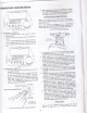
Sears owners manual M O D E LN O . ll3 .19771 SAWONLY 113.1977 5l S A WW I T HL E G S SeriaI Number M o d e la n d s e r i a l n u m b e rm a y b e f o u n d at the front of the base. Y o u s h o u l dr e c o r db o t h m o d e la n d s e r i a n l umber place in a safe for f u t u r eu s e . CAUTION: ReadGENERAL and ADDITIONAL SAFETY INSTRUCTIONS carefully IO-INCH RADIAL SAW o assemblV o operating o repair parts S o l d b y S E A R S , R O E B U C KA N D C O . , C h i c a g o ,l L . 6 0 6 8 4 U . S .
tools f o r P o w e r i n s t r u c t i o n s s o f e t Y g e ne r o l duringextendedPeriodsof protectors(Plugsor muffs) operation. 1 . K N O WY O U RP O W E RT O O L c a r e f u l l v '. L e a r n r t s ;i;;J the owner's manual a s w e l l a s t h e s p e c i fc a p p l i c a t i o na n O r i m l t a i i o n i t h istool' t o p e c u l i a r o o t e n t i ahl a z a r d s 1 3 .
addltional safety instructions for radial saws CAUTION: Always disconnect the power cord before removingthe guard,changingthe cutting tool, changingthe set-up or making adjustments. Shut off motor before performing layout work on the saw table. W A R N I N G : D O N O T C O N N E C TP O W E RC O R D U N T T L THE FOLLOWING STEPS HAVE BEEN SATISFACTORILY COMPLETED: l. Assemblyand alignment. l l .
additional safety instructionsfor radial saws removed from the saw arbor before using the a c c e s s o r ys h a f t ( r e a r e n d o f t h e s a w m o t o r ) . N E V E R o p e r a t et h e s a w w i t h c u t t i n g t o o l s ( i n c l u d i n gs a n d i n g a c c e s s o r i e si n ) s t a l l e do n b o t h e n d s o f t h e s a w a r b o r . (B) RIPPING 'l . Never apply the feed force to the section of the workpiece that will become the cut-off (free) piece.
WEAR YOUR The operation of any power tool can result in foreign objects being thrown into the eyes, which can resultin se.vgre9y9 damage.Always wear safety gogglescomplying with ANSI 287.1 (shownon packagetOJtorecommencing power tool operation.Safety Gogglesare availableat Seari retailor catalogstores. electrical connections POWERSUPPLY 1. Motorspecifications The A-C motor used in this saw is a capacitor-start. non-reversible type havingthe following specifications: Voftage eO/24O Amperes 11l1.
electricalconnections to a 240V is co-nnected d. Make certain the receptacle 2a0v circuit a !1nctr A-c power t'ppl;;;;Gh bv a1d-1;'otected itpacitv' havingat leastt,i'S-ttp' breaker' circuit a 1S-amp'trme-oelayfuseor MOTORSAFETYPROTECTION 5unc: "vacuumed"' blown out' or NOTE: This motor should be interferencewith normal freouently to prevent ;;ilil motor ventilation. al-reset' Y o u r s a w m o t o r i s e q u i p p e d, ytti t l ^ i .
over-heatingand motor burn-out, use the table below to determinethe minimum wire size(A.W.G.)extensioncord. Use only 3 wire extension cords which have 3 prong grounding type plugs and 3-pole receptacleswhich accept the tools plug. Wire Size Required . lAmerican Wire Gauge Numberl 240 Volt Line | 120 Volt Lines Up to 100 feet 100 feet to 200 feet 200 feet to 400 feet NOTE: For circuits of greaterlength,the wire sizemust be increasedproportionatelyin order to deliveramplevoltage to the saw motor.
CONTENTS Guarantee ......2 G e n e r aSl a f e t yI n s t r u c t i o nf os r P o w e rT o o l s . . . . . . . . . 2 A d d i t i o n aSl a f e t yI n s t r u c t i o nf os r R a d i aSl a w s . . . . . . . 3 ElectricalConnections ........5 AssemblyandAlignm . . e. .n t ........8 UnpackingandPreassembly... .:.... g AlignmentProcedure .......12 Locationand Functionsof Controls BasicSawOperations Adjustmentsto Conipensate for Wear Trouble-Shooting Maintenance and Lubrication . .
I The fof fowing parts are includedwith Model 113'197751. Key No. '| 2 3 4 5 5 6 6 6 7 8 I Table of Loose Parts L e g. . . L.H. .. Stiffener, R.H. . . Stiffener, LoosePartsBagPartno. o'si'S'Z' (containing items): thefollowing - Screw.Truis Hd. 114'20x5l8 - . . - Lockwasher, l/4 External - Lockwasher. 5/16External - Nut,Hex114'20. - N u t ,H e x J a m5 / 1 6 { 8 - Nut,Hex112-13. - Foot.Leveling - Screw, x 5/8 . HexHd.5/16-18 - W a s h e1r 1 . 1 3x2 l 1 / 1 6x 1 / 1 6 . . ,$a oty.
REMOVESKTDSFROM BASE MOUNTINGSAW 1. .FroT among the loose parts, find the following hardware: 8 8^ 16 8 Hex HeadScrews,5/16_1g x 5/g 5/.l6 in. exierna'tlype .Lockwashers, W a s h e r s1,1 / 3 2 t D H e xJ a m N u t s , 5 / l G l g 2. Placesaw on legsso that holesin bottom of saw line up with holesmarkedX in top of legs. 3. lnstall screws,washersand nuts asshown. lf you mount the saw on any other Craftsman baseor flat bench, make sure Elevation Crank has propei clearance to rotate.
assemblyand alignment BE positiveswitch is "OFF" and power cord unplugged thru-outentireprocedure. REMOVE CARRIAGE STOP SCREW, LOCKWASHER AND TAG. Read and understand warning tag before discarding. @t*ofi:fo LocKwAsHER 6p & , sToPscREw V*n'*rrt rillto*tt L O C KA R M B E F O R EP R O C E E D I N G . H O L D I N G C A R R I A G E A S S E M B L YW I T H B O T H HANDS, CAREFULLY START AND SLIDE THE C A R R I A G EO N T O T H E T R A C K S .
A L I G N M E N TP R O C E D U R E IMPORTANT: S Q U A R EH D . S C R E W s/16-18 x 3/4 T A B L EM O U N T I N G S U P P O RCTH A N N E L IN ORDERTO OBTAINMAX'MUMCUTT'NG ACCURACY,THE FOLLOWI'VGS'X STEPS M U S T B E C A R E F U L L YF O L L O W E D . BECOME THOROUGHLY FAMILIAR WITH THESESTEPSSO THAT YOU CAN ALWAYS MAINTAIN YOUR SAW 'N PROPER ALIGNMENT.THE ACCIJRACYOF EACH ADJUSTMENT 'S ALWAYS DEPENDENT OF THEPRECEDING UPONTHE ACCIJRACY ADJUSTMENT.
assembfyand alignment F R O N TT A B L T INSTALLATTONOF FRONT (WORK) TABLE. EOITOMS O F I 1. Placefront table board upsidedown -ir,J'iJr., on a workbenchor on the f loor. Drive f_"ui into that is not counterbored. 2. Align the counterbored .holeswith matchingholes in support channels. Instail the tir:" l)ifil'"tnch flat washers,and four % _.2g " ii""i.,-p#-'H?o macnine screvvs. Just baretystart the poin;;;;'r;"ie"w and the one(1)%- 20x 1-3/4 gup pii inch 3.
3. L,oosen(2') % - 20 Gib set screwson the left side rearof the columnsupport. at the 4. Elevate,and then _ . , . " ^ r , , , . (a) r r rthe r d , if n e ccolumn olumn bincts b i n d s :nrr a n d -,-.,-.,^-t?y:,l,lh".Arm: e l e v a t i o nl ; loosen two 5/16 _ id Dtarprr nr,+. ^^ 3_-_^ .diffic-ult j:,;"1; jl.it,iil.-ii;;";;ilT# 3:i1,1^ly::^"1 but firm-.r.r.,i"".'i6) tf ths I:,i,j:T"::^.rT::,1 -- *iir, i" ff uurumnsupport, H;,i::ilo",l; n,r1g,nf:^,:o; tighten :.,iJ" the two s/16 - lg.plated 5.
assemblyand alignment 3. Lower arm until saw blade iust clearsthe front table. Lock the yoke clamphandleand bevellock lever. 4 . Place a framing square on the table as shown and position the bladeand squareuntil the legof the square just contactsa tooth of the blade.Mark this tooth. must be NOTE: The framing (or combination)"square Assembly and "lrue" see start of Alignment" section on p' 8 for checking method." 5.
STEPFOUR S O U A R I N GS A W B L A D E T O ( W O R K ) T A B L E NOTE: lf alignmentprocedurestep onewas not performed, this adjustmentcan not be accomplished. 1. Placea framing squareon the table with the short leg againstthe saw blade.Do not allow the squareto rest "set-out" tooth; it must rest flat againstthe againsta bladeside. 2. lf the saw blade is squarewith the table top (no visible gap appearsbetween the saw blade and square)arld no is required. Set bevel indicator to 0o iolrti-.nt reading.
assemblyand alignment 3. To correct"heel" conditionproceedasfollows: a. b. c. d. Removeleft hand carriagecover. Loosenthe yoke clamphandle. Loosen(slightly)the two hex-head screws. Rotate the yoke assemblyuntil gap between the sawbladeand squareis eliminated. e. Lock yoke clamp handle and retighten the two hex-headscrews. f. Recheckfor "heel" and installcarriagecover. g. Loosencarriagelock knob.
STEPSIX 1. INSTALLING AND ADJUSTING RIP SCALE INDICATORS. NOTE: The rip scalesand pointersare intendedto be used for quick settings.For greateraccuracy, take direct measurement betweenbladeand fence. indicatorand twin nut, loosenbut do a. Pre-assemble not removethe two screwswhich attach left hand carriagecover. b. Tilt carriagecoverand installrip indicatorasshown. Tightencarriageattachingscrews. c. Loosen but do not removecarriagelock knob in right hand carriagecover.Installrip indicatorin the samemanner.
assemblYand alignment A L I G N M E N TO F S P R E A D E RF O R R I P P I N G ' GUARD OR W A R N I N G : N E V E R P O S I T I O NT H E NoR wlrH PowERoN; ir,r'iiiiickaAcKAssEMBLY pdi;iioN-attrrlrrcreAcr PAWLsBY GRASPING P A W L SO R S P R E A D E R . 2. Install BladeGuard. of a. Sight (visually)to check for proper alignment is spreader the lf shown' as blade saw ipieaOerwith not aligned,adjustit asfollows: (1) Loosen two hex nuts' one on each side of sPreader.
rocationsand functions of contrors The versatility of the Rad.ial Saw is due, in part. to its andthese .r._lh1 :"^:::"lrt ,[:iilJ",.'::Jhe t"v, io i"-rJJ..rrrr,operation. controIs tot . rr op.ruiio-n"r"i"ro r. actua ||y A s e r i e so f s i x d i a q r a m ",m **l.il' ;;:i.'i;l:"","..Xi1;; *:,TS.' :::ffiTJj: set-ups and !. operatino tamiliar with thesedia-qrams ,procedurer. io, Jf.lortd become t h a t f o l l o w , b e f o r eo p e i a t i n gand the oo.i.,lni Instructions y o u r, . * l - " , " .
locations and functions of controls saw-blade(bevel) angle, are: bevel lock leverand lever. bevel-index b. The bevel-indexscaleindicatesthe angularposition of the motor with respectto horizontal,from 0o to 90o in eitherverticalPosition. c. The bevel index lever automaticallyindexes the motor at 0o, 45o and 90o. Move bevelindex lever to the left while positioningthe blade,then release it. At any other positionit doesnot engage. d.
W A R N I N G : F O R Y O U R O W NS A F E T Y A L W A Y S "OFF" WHEN SAW IS NOT LOCK THE SWITCH t N U S E .R E M O V EK E Y A N D K E E PI T I N A S A F E PLACE. . . ALSO IN THE EVENTOF A POWER F A I L U R E { A L L Y O U R L I G H T SG O O U T ) T U R N S W ] T C HO F F . L O C K I T A N D R E M O V ET H E K E Y THIS WILL PREVENT THE SAW FROM STARTING UP AGAIN WHEN THE POWER C O M E SB A C K O N . Spreader -to prevent kerf from closing in on sawblade and possible kickback; - to prevent "wrong-way feed".
HAVE YOUFOLLOWEDALLS'XSTEPSOF THE ALIGNMENTPROCEDI'RE?IF YOU HAVE NOT FOLLOWED THEM IIT rNfuN PROPER SEQUEVCE, YO'I CENNbT EXPECTACCURATECI'TTING NESUIiS. In addition to, the proper alignment of your saw, you musr a l s o b e c o m e f a m i l i a r w i t h t h e f o l l o w i n g p r a c t i c e si n o r d e r to expect the best results. I t THISEDGEOF BOARD AGAINSTFENCEFOR ALL CUTS 1.
basic saw operations REOUIREMENTSFORCROSSCUT Board position (stationary) against rip fence (guide) and l a y i n gf l a t o n t a b l e t o p . (OPERATIONS 1 THROUGH 4} 1. Arbor nut must be tight and saw blade guard installed i n h o r i z o n t a lp o s i t i o n . 2. Arm control lever must be in locked position. 3. Adjust the antikickback assemblyso the pawls just clear the workpiece or the fence, whichever is higher. 4. Work must be held firmly against table and fence.
basic saw operations OPERATION N o . 2 - M I T E RC R O S S C U T Miter crosscuttingis the processof sawinga board at any angleother than a 90o (square)cut. The 45o miter angleis a popular one, since two boards cut to 45o can be assembled to form a 90o cornerfor producinga squareor rectangularframe.The radial arm is set to the desiredangle of cut; yoke and bevelsettingsindexedat 0o (andlocked) as in squarecrosscutting.
R E O UR I E M E N TW S H E NR I P P I N G (OPERATIONS 5 AND 5) 1. Carriagelock knob must be locked. 2. Radialarm must be lockedin 0o position. 3. Work must be held firmly againsttableand fencewhile feedingthrough. 4. Guard spreaderand antikickbackmechanismmust be p r o p e r l y s e t . O B S E R V E I N S T R U C T I O N Sl N P A R A G R A P H , " P O S I T I O N I N GG U A R D . A N D A N T I K I C K B A C KA N D S P R E A D E R A S S E M B L YF O R RIPPING"UNDER "LOCATION AND FUNCTION OF CONTROLS". 5.
2. Sincethe work is pushedalongthe fence,it must havea straightedgein order to make slidingcontactwith the fence.Also, the work must makesolidcontactwith the table, so that it will not wobble.Providea straightedge, e v e n i f t h i s m e a n st e m p o r a r i l yn a i l i n go f a n a u x i l i a r y straight-edged board to the work. lf the workpiece is warped,turn the hollow sidedown. 3.
adjustments to compensate for wear ADJUSTING BEVEL LOCK LEVER r--=-\. 1. The purpose of this lever is to lock the moror at any angle. To adjust, remove the set screw with wrench as shown. Use the bevel lever as , *r.n.n to tighten -lock the clamp bolt. Do Not Over fight"n. R'.ptace bevel lock lever in locked position anO ilgl_,t"n the 5s1sqrsM/. \ N EEVELLOCK LEVER w / E V I I t/8 HEX ''1" WRENCH EEVELLOCK LEVER I N L O C K E DP O S I T I O N YOKE LOCK HANDLE ADJUSTMENT. 1.
adiustmentsto compensatefor wear ARM TO COLUMN 1. With the arm control lever unlocked and in index releaseposition,the arm should move firmly with no verticalplay in the arm. The arm shouldfit snuglyon the column. lf not. then adjust. a. Removetwo (2) screwsfrom rear cover plate and tighten evenly top two 3/8-16 bolts, until arm movesfirmly and there is no verticalor horizontal movementin the arm when arm control lever is l o c k e do r u n l o c k e d .
A R M L O C KA D J U S T I N GW H E E L Arm control lever operatesa brake shoe that locks and the arm index releases the arm, and automaticallyreleases pin for 0o & 45o miter settings. The lock action shouldfeel tight and secure.Considerable amount of effort must be appliedto the leverto lock the arm. N O T E : L e v e rm u s t b e i n u n l o c k e dp o s i t i o nw h i l e m a k i n g adjustment.
trouble-shooting F I N I S HC U T E N D l$'$ 1. RADIAL SAW DOES NOT MAKE ACCURATE 0o or 450 MTTERCROSSCUTS. a. Looseness between column tube and column support. Align as describedin Alignment'procedure Section Step Two. b. Crosscuttravel not properly adjusted. R efer to Step Three in Alignment procedure SectionSquaringCrosscutTravel. c. Column is Loosein Support. Referto StepTwo in Alignmentprocedure.
trouble-shooting I N RIP POSITION 5. WOOD BINDS, SMOKES AND MOTOR SLOWS DOWN OR STOPSWHEN RIPPING. a. Dull blade or warpedboard. Sharpen or replace the saw blade. Avoid the attempteduseof severlywarpedmaterial. b. Feed rate too fast. Slow Feed Rate. T O P V I E W W I I H ARM 9OO TO THE FENCE / \ - \-l FENCE \I FEED DIRECTION <- c. Saw blade heels. C h e c k a n d a l i g n a s d e s c r i b e di n A l i g n m e n t ProcedureSection,Step Five. d. Fence not straight. Replacefence. e.
CHART MOTORTROUBLE'SHOOTING particularly tgt NOTE:Motorsusd on wood-working -"I: woodchips to tne accumu'|il;;isivdust'anO susceptible to ot '"""'umed"',frequently and shouldbe blown-oit ventilatton' motor with normal il;";;i;;"rence REMEDY SUGGESTED Motor will not run. 1. ProtectoroPen;circuit broken. 2. Low voltage. Motor will not run and "BLOW". fuses Motor fails to develoP full power. (Poweroutput of .otot decreasesraPidlY with decreasein voltage at motor terminals.
maintenanceand lubrication MAINTENANCE N O L U B R I C A T I O NR E O U I R E D W A R N I N G : F O R Y O U R O W N S A F E T Y ,T U R N S W I T C H "OFF" A N D R E M O V E P L U G F R O M P O W E RS O U R C E OUTLET BEFORE MAINTAINING OR LUBRICATING YOUR SAW. When you receive your new Craftsman radial saw, it requiresno lubrication.The radial saw has been partially alignedand all bearingsare lubricatedand sealedfor life.
repair parts PARTSLIST FOR CRAFTSMANlO.INCHRADIAL SAW MODEL 113.197751 o s 4 6- ll &- t2 o;;f;, o a o o o FIGUREl_LEGSET Key No. 1 2 4 E o 7 I o 10 11 12 * Part No. 63749 60314 63751 63750 sTD 551225 sTD 541025 sTD 523106 sTD 551031 sTD 55'l131 srD 541231 sTD 541250 | 803835 I 63752 I Description Leg x5/8 Screw.TrussHd. 114-2O Stiffener,R.l-.|. Stiffener,L.H. *Lockwasher,External1/4 *Nut, Hex 114-2O *ScrewH , e x H d .
repair parts rr U /i F = @ -1 r.o
- - 7 ^ (\I (') CL a, o o { I frE€E (o EE-+E "g n ; sSs ZZZ=, :; *S ti or dg;.=e ee?=i ,-l-r *^;? : F ) x xO *ql \ s rl) \ x s v e sf :f . : I e i r * E i F : ' - --E= * = * ' * € 6 d : 9 5 * E T ; # ; F E : f f f 6 & E f iH g =:iii p pi s$! !.;gg:.Fq?t?t-=€Ei'i #FgSggsBsB s.t5coE = . n,t32?pE r\C .L P 3 3 6 .- AR o5 < i E E : s p eI -t E2 eFEnngn;E ;EEBilgEEAAfi$$E Ip I 6< Is z r N €5 5 (9 o; =z =t\ E g 9P i!; f( Jfafo E> ?.= F J vr!'/.
repair parts /P-3 ,'^f-e t u ) { r t \ b-Z* R--e \ / 4-,F / . / = CN \\ .D Ob o \ \\\ rtuo+) \' \ 9; =z o < FF \------\ =E Ei / / ./-\ \ / ; / \\Ii . ' , a \\" \\ ks ? ; 3 3h U -/V/ * 9 l tt l/\\ l t l t I ,l-. ^ s r l l er o
P E P N \ $ (o o CL (t (l' o 9S x N i i? I =S x S : lcr o : cc o..d T ::_ ( ; " 1 N : i 3 < ; g i : ; Ei E€ i S ;Ii s a -^'fFi ^E*rt E F F € € ; S : E F i a g o e : Ir Ii X=' . , iI.B- ; €d SEF : r ; - . d E'F. :8 ; a. €: e Fii -'- o o.C !, o X o = ;,P ;.: i'' E i.9t#i , t8.di= H-i$ - E . i ?q€F, i;F! i:;E;i:€€ tqq:c€ t:s r *; - ^ .* * E E f; ! : E i c * E0 € Es A E EE s$ E - s = g9 # sr atzsE-}-;E$F-.F s.s,rs e3"EFE"Hi ! = * * * * r * .
repair parts $ o (r' N (? -St ---d-s \ fr \ \ \ \ \\ G, tf $ ! t = o ) I< (EF o5 < Ea) I a T 1ta! I I o G' 9o =z o< S 9 9 S r = R =o \ al--A \ \ \ ,lh u,*uj-\ttrg,l a ?n l,l- - tr
ass -q : :ii gi: Es: ES9.E E -E E;r ; S p T . q? [ s s o CL 0 (D o E t ' r sP. E ;? g _ i ;e t s € a * a - - . g t q;ig ; ; s i,irt€ i{i!';qis € ;;r gs g g* g g $;ei:F g ;! g ; i sssg! : s I E v) -16 : 6B B ro or 5 rrl5ro $ 6 rr, cor- e E ui. S 3 - r 3 il 3 sr e o.)3 3 S 3 d.
repair parts PARTSLIST FOR CRAFTSMANlO.INCHRADIAL SAW MODEL NUMBER 113.19771AND 1 13.197751 13 14 \ l t5 / bb+- I l5 I IF THIS PARTIS REMOVED, D I S C A R DA N D R E P L A C E WITH A NEW PUSH NUT. 25 tT"*F -f [[-----1i";' i' Y*g@ .-Y><5 s_-5 FIGURE5_ARMASSEMBLY Key No. Part No. 'I 63626 2 63629 63631 4 63628 9420417 o 63627 63632 63630 Key No. Description 20 21 22 23 H o u s i n gP, i n P i n ,A r m I n d e x Shoe,Arm Lock S p r i n gT , ension *Screw, Type "T" Hex WasherHd.
PARTSLIST FOR CRAFTSMAN1O-INCHRADIAI. SAW MODEL NUMBER113.19771AND 113.197751 2 II -@ ,rt .--Jg" t\ 8 9 15 14 9 t6 12 / F I G U R E6 _ G U A R DA S S E M B L Y Key No. Part No. Key No. Description 1 2 3 4 5 6 Guard 63681 *Nut, Square,5/16'18 120399 Bar,Antikickback 6391 Guide,Antikickback 63540 *Washer, 13/64 x 5/8 x'l /32 sTD 551010 *Screw,Type "T" Pan Hd. sTD 601103 7 I Screw,Wing5/1G18 x 1/2 60219 *Nut, H e x .
Sears owners manual SERVICE M O D E LN O . ll3.l977l S A WO N L Y Il3.l9775l IO-INCHRADIALSAW N o w t h a t y o u h a v e p u r c h a s e ydo u r 1 0 - i n c hr a d i a rs a w ,s h o u r d a need ever exist for repair parts or service,simply contact any sears service center and most sears, Roebuckand co. stores. B e s u r et o p r o v i d ea l l p e r t i n e n tf a c t sw h e n y o u c a l l o r v i s i t .