{" salesmanship For Future Reference owner's manual MODEL NO. 509344 509345 509344 FITS THE FOLLOWING RADIAL SAWS: 113.198110, 113.198114, 113.188210, 113.198211, 113.198250, 113.198251, 500345 FITS THE FOLLOWING RADIAL SAWS: 113.198310, 113.198311, 113.188410, 113.198411, ! ® 113.198510, 113.198511, 113.198610, 113.
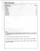
Table of Contents sl Safely. ol 3 Assembly 12 .Alignment: 27 “Controls 28 Crosscutting 32 Ripping. ini. . . 36 Cutting Aides 45 Maintenance Repair Parts . 49 NOTE: T.This ail i is interlard 10, be used al ong with ‘your +r original saw manual. if you no longer have your saws owners manual, call customer service at 1-800-326-1184. Have your saw's model number when you call, 2. if you require this manual in Spanish or French, call 1-800-511-2628. Si necessitate est manual en espalier; lame al 1-800-511-2628.
Safety This manual has safety information and instructions to help users eliminate or reduce the risk of accidents and injuries, including: VE 1. Severe cuts; and loss of fingers or other body parts due to contact with the blade. 2. Eye impact injuries and blindness, from being hit by a thrown work piece, work piece chips or pieces of blade. 3. Bodily impact injuries, broken bones and internal organ damage from being hit by a thrown work piece. 4. Shock or electrocution. 5. Burns.
: work pie back toward tho user ruing ee ping: : The: cause of Kickback is the binding. or pinching of the blade in the work piece. Sev: real conditions can cause the blade. to bind or pinch: When a work piece kicks back, it could hit hard enough to cause internal organ injury, broken bones, or death. Read and follow the information and instructions under ripping safety. Wrong Way Feed Hazard Wrong way feed is ripping by feeding the work piece into thé! out feed side of the blade.
Safety Guard Function and Features The guard is a very important safety feature, designed to reduce ihe risk of injury associated with blade contact. Install the guard correctly, Follow the specific instructions in the ripping and crosscutting sections to sei and use the guard correctly for each type of cut. Guard Features Include: 1. A non-movable metal upper portion, (Upper Guard} which is fastened to the motor by the guard clamp screw, and which fully covers the upper half of the blade. 2.
it of paws t to be lowered to the work: piece Stalactite for ripping. They allow the; i work piece to pass freely from indeed fo out: feed side; but help stop the kickback motion from: quieted to indeed side by grabbing into: the work piece surface. Pawls must be reset each time a different thickness work piece is cut. 7. A guard tab to manually raise the plastic guard at the start of ripping unusual work pieces whose size/shape do not cause the guard to raise automatically.
Safety Safety Instructions Read and follow all safety instructions. Personal Safety Instructions 1. Wear safety goggles labeled ANSI 287.1 (or in Canada CSA on the package. it means the goggles nest impact standards set by the American National Standards Institute. Regular eyeglasses are not safety goggles. 2. Wear close fitting clothes, short sleeved shirts, and non-slip shoes. Tie up long hair, Do not wear gloves, ties, jewelry, loose clothing, or long sleeves.
| Saw Safety instructions 1 Use gal f pawls and riving knife ac Cording to instrictiols. Keep them in working Dastard, : 2. Routinely check saw for broken or damaged.parts, Repair or replace damaged parts before using saw. Check new or repaired parts for alignment, binding, and correct installation. 3. Unplug saw before doing maintenance, making adjustments, correcting alignment, oF changing blades. 4. Do not force saw. Use saw, blades and accessories only as intended. 5.
Safety 3. Rip only work pieces longer than the diameter of the blade. Do not 7ip work pieces that are shorter than the diameter of the blade being used. 4. Work pieces that extend beyond the saw table can shift, twist, ise up from the table, or fall as they are cut or afterwards. Support work piece with table extensions the same height as the saw table. 5. To prevent tipping, support outer ends of extensions with sturdy legs or an outrigger. 6.
Safety : 10 On-Product Safety Labels There are several safety labels on the saw. They alert the user to hazards explained in | thermonuclear remind the user how to + avoid the.
Near the saw handle is this safety label to alert you to thrown objects ang to remind you to wear safety goggles: On the clear plastic guard is this OSHA required label: On the bottom surface of the motor, visible when the cutting tool is horizontal, is this safety label alerting you to use a guard when edge molding, and to position the cutting tool behind the fence: (see Accessories Section) rm Safety A WARNING INADVERTENCE ADVERTISEMENT WARNING/ INADVERTENCE / ADVERTISEMENT To avoid ny Para Evita nosiness
Assembly Identify. Parts [The following patisserie included: Note: Before beginning assembly check that all parts are included, If you are missing any part, do not; assemble guard. Contact your Emerson Tool Company Service Center at 1-800-326-1184 lo Fogged the missing part, Sometimes small pairs can get lost in packaging material. Do not throw away 1 any. packaging unit gi ard is put together.
Assembly Ah warning Ah warning Plugging in saw during assembly This retro fit guard kit required addiction result in electrical shock, or tonal clearance behind fence. New severe cuts rom Contact with spinning table boards are being supplied for blade. this reason. Do not plug in saw at any time during assembly. Plug in saw only when iris to be used. Remove Saw blade and Guard 1. Tighten carriage lock knob, 2. Loosen guard clamp screw, remove guard. 3. Motor shaft has left hand threads.
1 stalling Table Boards (40* wide Modern) Ford (40 Wide Wide Models Skip to Page 17 able Supports Pi roe 1. Allah a table support to each side of the saw using. the four hex head bolts and flat i.washers, Puttee bolts through the center of the enlarged holes in the table supports so that the supports may slide up or down as needed: Put a lock washer and hex nut on each bolt-sand hand tighten.
Assembly Installing Front Table 1. Set out: front table tee nut 14" Us clip 114” diam. x 7/8" long cup point set S Crew four 1/4" diam. x 1" long pan head S Crews 1/4" dia. x long pan head screw five 17/64" LD. x 5/8" 0.0. flat washers four 1/4" lock washers ~ four 1/4" diam. hex nuts 2. identify top and bottom of table: top has counterpoised holes. Place table bottom side up on solid surface. Hammer tee nut into leveling hole. (This hole is not counter bored from the top). 3.
Assembly Make Front Table Fiat 1. Place rear table on its edge, across ¢enter of front table, Check for gap between sulfates, Fi : if there is less than 1/32% gap, tighten cup point set screw until it touches frame (gook underneath table), then tighten center font pan head screw. H.there is more than 1/32" gap, close gap by raising-OT dowering center of front table: to raise center, tighten cup point set screw against frame; to lower center, tighten center long) pan head screw. 2.
Assembly Installing Table Boards (44" Wide Models) Installing Front Table 1. Position the front table and insert the front two screws. The rear screw holes in the table do not line up on any holes in the saw base. 2. Using the rear screw holes as a drill guide, drill a 5/18” hole in the saw base for each of the two rear screws. 3. Remove the front table. 4. The U-Clips that were used as news for the rear screws must be moved to the new screw location.
Assembly rand the front fable on one edge. Put a Ath a washer through each the mounting screws line up with the U-clips. The. front table should extend about one inch beyond the trim caps. 9. Start the mounting screws into the Clips using a Phillips screwdriver. Tighten the screws until the heads are just touching the table. Make sure that the table is not squeezing'thezubber grommets. AO Start the leveling screws into the leveling holes using a 1/8 inch hex “L” wrench.
Assembly 3. Unlock the bevel dock to release the motor. Hold onto the motor as you do this. Ah caution: The motor is heavy and can swing down quickly. You can be cut or Injured if the arbor shaft hits you. Hold the motor when you unfrock the bevel lock, 4. Turn the motor until the arbor shaft is pointing straight down toward the table. 5. Lock the bevel lock to hold the motor in this position. 6. Draw two lines on the front table, over the table rails. 7.
the handle end of the arbor rich over this point and lower the arm until the arbor shaft is just touching the “winch: The wretch should slide back and forth with slight contact, : 18: Move the arbor shaft over another point. D6 rice change the elevation of the arm. 19. Tightener mounting scows and/or Reveling screws until the handle of the arbor wrench just fits between this point and the driveshaft. The ostrich should slide back and forth with slight contact.
Assembly 1. Pull motor/carriage to end of arm and lock the rip lock. Rotate motor to out-rip position. ) 2. On the rear of the motor is located the motor support cap. Remove this cap. A small screwdriver will assist you in removal of this cap. {This cap is not on all models) 3. Using a 3/4" socket, short extension and ratchet remove nut and washer from motor support. Take care not to drop washer from motor support.
1. Novel spring wedge “g. Bevel lock knob h Strew, pan head plaster no. 8 x 3/8" long 8. Remove’ the bevel spring wedge from this assembly by rotating shaft support coin counterclockwise until it comes out of the square nut located between the bevel lock lever and the bevel'spring wedge. Do not remove any other items. Remove square nut then remove the bevel spring wedge from the bevel lock lever.
Assembly 13. Using the two #8 x 3/4 pan head screws provided, attach the new handle in the same way as the old one was removed. 14. Inspect motor support cone on yoke, and cone on motor for lubrication on contacting surfaces. These surfaces should be generously lubricated. If necessary lubricate with lithium white grease (hot supplied). 15. Reinstall motor on motor support. Line up the index pin with the slot in the index plate. Reinstall the 505 x 7/8 x 1/16 washer and 1/213 lockout.
Assembly Lb Installing Guard Adapter a ‘Remove the top motor cover seize and . lock washier. Keep the washer. Discard the old screw. eG z Install the adapter. The Wo ends of the 1 adapter fit into the center cooling slots of the motor, then the adapter is rotated up into + place. 3. install the replacement screw (#6 x 1/2") with the old-lock washer into the top motor cover hole. This locks the adapter in place.
Assembly Installing Blade/Squaring Crosscut Travel NOTE: This adjustment helps ensure the blade accurately travels square to the rip fence. 1. Index arm at 0° miter and lock. 2. Install saw blade as shown. Motor shaft has left handed threads turn nut counterclockwise to tighten. Beaumont: Do not over tighten arbor nut. Use arbor wrench to “snug” nut in place. Over tightening could distort the bide collars and cause blade to wobble. 3. Lower arm until saw blade just clears the front table.
table 2.Tilt clamp forward and snap into place in opening at rear of table support. “3. Repeat steps for other table clamp: install Guard Bey * The guard is a very important safety feature. © It covers a large part of the blade and helps install Fence, Rear Tables, and Table Clamps... on ] Insert fence, the spacer table, then'rear 4. Tighten thumbscrews to clamp table sec: sons in place. : (Steps 2, 3 and 4 only apply to remodels with 40" wide table boards.) protect against severe outs.
Alignment Guard Installation Steps/Align Riving Knife to Blade The goal of this adjustment is to position the riving knife directly in line with the blade. Riving knife alignment is an important safety factor. The riving knife rides in the serf of the cut work piece during ripping to keep the two sides of the work piece from pinching on the blade. Blade pinching is a cause of kickback. 1. Lock yoke in in-tip position (blade towards column, motor towards front of arm). 2.
On-Off Switch Bevel Lock Lever Hand wheel Cont Function Operation/Comments Miter Lock Frees radial arm to move; locks in. Pauli out and towards right to unfrock, any desired position; per-set push to lock. indexed positions at 0°, 45°L, 45°R Hold in unlocked position while moi i ing arm On-Off Switch.
Controls Rip Scale & Rip indicators Saw Handle Control Rip Lock * Rip Scale & Rip Indicators (Not Electronic Models) Swivel Lock Table Clamp Thumbscrew (Leg Set Model) Saw Handle * NOTE: After installing new guard and new table boards rip fence scale is no longer correct. Measure distance between thence and blade when saw is in rip position.
Controls Hold Down Control Guard Clamp Screw Guard Hold Down Knob Hold Down Riving Knife Bracket Unction Secures guard to motor; frees guard for removal Protects against contact with upper blade; partially protects against contact with lower blade; acts as sawdust deflector Frees hold down to move up and down; locks hold down in place During ripping, acts as partial barrier to indeed side of blade; keeps indeed side of work piece from fluttering; acts as sawdust deflector Prevents side to side movement of r
Controls Passivizing Knife Knob Paris Control Guard Tab Pawls/Riving Knife Knob Pawls Riving Knife Riving Knife Function Provides manual way to raise clear plastic guard during ripping when work piece fails to raise it Frees pawls and riving knife to independently move up and down During ripping, slow or stop kickback by digging into work piece; when lowered during crosscutting, provide partial barrier to leading edge of blade Reduces kickback by keeping serf open; when lowered during crosscutting, provides
Crosscutting Defined Crosscutting is curling a work piece to length. The work piece is held firmly against the “thence; and the blade is pulled through the -Work piece to make the cut. Straight; bevel, miter, dnd compound cuts can be made. Crosscutting Safety The hazards associated with crosscutting include: exposed blade teeth, rolling carriage, and thrown work piece. This section explains these hazards and tells how to avoid then or reduce the risk of their happening.
Crosscutting Crosscut Serfs A serf or shallow cut is needed in the table and fence to serve as a path for the blade and to ensure that the blade cuts all the way through the work piece. A serf is needed for each different cutting path. To make an approximately 1/16” deep Keri: 1. Prepare table: put fence in front position tighten table clamps 2.
_ Crosscutting ‘Making Crosscuts : Follow these steps to make crosscuts. J 510 Prepare table: : = put fence. in front position a tighten table clamps 2. Prepare blade! «Sock motor ity crosscut position lock radial arm at desired miter angle cock mayor at desired bevel angle* unlock carriage lock and push blade to rearmost position, behind fence lower blade into serf* but not touching serf bosom (blade should move freely).
Crosscutting Repetitive Crosscutting Repetitive crosscutting is the repeated and continuous cutting of many pieces of lumber io the same length. Carriage and length stops can help make this type of crosscutting more efficient. A carriage stop defines the distance needed to pull the blade through to complete each cut. This will prevent pulling the blade through more than the recommended distance.
ng ts hid The work piece is ade, which. rotates ina fixed guide for the earpiece. Place in the front position for narrower OF in the fear position for wider ip and trip refer. to blade position. 2 n-rip: the blade is toward the column, and the motor is toward the table front. In-rip is recommended because this position allows | better Visibility of the work piece and your hands. Use in rip when you set the blade 1/2 i “t0:16" from the fence.
Work piece Positioning Always set up so that the wider part of the work piece is between the blade and fence, This gives you greater clearance for push sticks, and allows better stability for feeding the work piece. Push Sticks and Push Blocks Use push sticks and push blocks instead of the hands to push the work piece through to complete cuts. They help keep hands away from the blade, A push block is used with an auxiliary fence. (see Cutting Aides).
uttered Zone Hazard Enhancer ‘Rotational: force of. blade can pull “i: hands: and ‘fingers back into’ blade. Touching; holding, -or pulling on outlived side of work piece while blade is Stl spinning will ‘result in fingers, +. hand or arm being cut off. To reduce “risk of out feed hazard: v Set pawls and riving knife; they act as partial barrier to out feed side. + Start dins finish cut from indeed sid. Keep both hands on indeed side. Keep hands away from out feed side.
Ripping To reduce risk of Kickback: + Set pawls and riving knife according to ripping set-up procedure. Correctly set riving knife is more {likely to prevent work piece from binding or pinching blade; correctly set pawls are more likely to grab into work piece to stop or stow kickback if one happens. v Check that riving knife is in line with blade {see Alignment: Riving Knife to Blade). v Cut only straight work pieces so surface wilt ie flat on table and edge will stay tight against fence.
= Hold Down Infinitude, & hold down must be sot correctly during ping to act as barrier against the indeed “| side of the blade, 16. help keep the work piece fiat on the tactile, and to deflect work piece “chips. lt must be lowered to just clear the : work piece. The hold down must be re-set each time a «different thickness work piece is cut. Follow the Ripping Set-Up Procedure to correctly set the-hold down.
Ripping Ripping Set-up Procedure Follow these steps before ripping. These steps must be repeated each time a different thickness work piece is ripped. A serf must be made for each different width cut. Also see the special notes for bevel set-up that follow this section, 1. Prepare table: insert solid {no keels) fence (Note: Use auxiliary fence when blade is set 1/2 to 2" from fence (See Cutting Aides) ~ tighten table clamps. 2.
an to support work pieces because this can cause kickback and it exposes helper {to potential lizards at out feed side. Special Notes for Be vat Set-Up centurion Bevel ripping creates unique problems of ‘visibility. .and feeding, Before out‘ting, check the set-up using both in-rip :. sand out-rip. Use the position that gives © /anesthetist combination of work piece visibility and push stick clearance. dig Bevel the edge that Is not against the _ Hence. ’ 1.
2. Insert yellow key and turn saw on. 3. Stand at indeed side and out of line of work piece, in case of kickback. Start and finish cut from indeed side. 4. Put work piece on table, in front of hold down, and tight against fence. To hold workplace in position, put deft hand on table, at least 8” in front of hold down, and lightly | “esgm™ press fingers against work piece. Support work piece with table extension or right hand.
oo Accessories for. information on safety, initiation ‘and use of dado blades and : dying i 8 16 use of a dido blade or molding “head in the horizontal position. iris an 3 advanced technique that requires a molding ‘head guard and a special fence. See Aces‘ dories for information on safety, installation analyses of dado blades and molding heads Cor edging: ! See Cutting Aides for information ori making the special fence. Ripping Hints 1.
Cutting Aides Before cutting any wood on your saw, study all of the Crosscutting and Ripping Instructions found on pages 45 through 57. As you learn new radial arm saw woodworking tech. piques, you'll see that many types of cuts need different support and feeding devices, known as jigs or fixtures. They can help vou make cuts more accurately. By helping to steady the work piece and keep you away from the blade, they can help you safely use your saw for certain cuts.
e Handle: er crossest 2 piece of 3/4" thick plod to the shape and size shown. The d comers cane any size that looks e drawing (about by ing it together: =. Using goo quality wood working glue, glue the strip saved earlier to the base as shown. Important: Do not use Tails or screws. This is to prevent dulling the saw blade in the event you cut into ¢ push bicycle « Position the handle at the edge of the ply wood base as shown, Fasten them together with glue and wood screws.
Cutting Aides Clamp the weatherboard to the front table, so that the angled edge of the weatherboard is against the work piece on the indeed side of the blade. Do not clamp the weatherboard against the cut off part (out-feed side) of the work piece. if clamped to the out feed side, the weatherboard can squeeze the kettle closed, put binding pressure on the blade, and cause kickback.
ake site the teeth of the pawls are always sharp, if they become dull the pawls must be A replaced: ; 1 Use 7/18" Erich movement hex nut. Remove old pies. 1 2. Install new pals, Place spacers exactly as shown: : Reinstall hex nut; + heck that pawls work freely, Lubricating Blade Guard Assembly : guard becomes difficult 1 raise: .1. Clean sawdust from the slot and slider. 2: Re grease with a small amount of light grease applied tithe slot and slider.
owner's manual MODEL NO. 509344 509345 \. © 2000 Emerson Electric Co. Part No, $P5g82 J 10-INCH RADIAL SAW GUARD KIT For Customer Service Questions or Replacement Parts Cal 1-800-325-1184 NOTE: 1. This manual is intended to be used along with your original saw manual. If you no longer have your saw's owners manual, call customer service at 1-800-325-1184. Have your saw’s model number when you call, 2. If you require this manual in Spanish or French, call 1-800-511-2628.