Operator’s Manual 12 in. SLIDING COMPOUND ® MITER SAW WITH LASER TRAC Model No. 137.212390 0 450 33.9 250 00 ϥ ϥ ϥ ϥ ϥ CAUTION: Before using this Miter Saw, read this manual and follow all its Safety Rules and Operating Instructions Customer Help Line For Technical Support 1-800-843-1682 Safety Instructions Installation Operation Maintenance Parts List Sears Parts & Repair Center 1-800-488-1222 Sears, Roebuck and Co., Hoffman Estates, lL 60179 USA Visit our Craftsman website: www.sears.
TABLE OF CONTENTS SECTION Warranty ............................................................................................... Product Specifications .......................................................................... Symbols................................................................................................. Power Tool Safety ................................................................................ Compound Miter Saw Safety ......................................................
WARRANTY CRAFTSMAN ONE YEAR FULL WARRANTY If this Craftsman tool fails due to a defect in material or workmanship within one year from the date of purchase, call 1-800-4-MY-HOME R to arrange for free repair (or replacement if repair proves impossible). This warranty applies for only 90 days from the date of purchase if this product is ever used for commercial or rental purposes. This warranty does not include expendable parts, such as lamps, batteries, bits or blades.
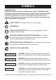
SYMBOLS WARNING ICONS Your power tool and its Owner’s Manual may contain “WARNING ICONS” (a picture symbol intended to alert you to, and/or instruct you how to avoid, a potentially hazardous condition). Understanding and heeding these symbols will help you operate your tool better and safer. Shown below are some of the symbols you may see. SAFETY ALERT: Precautions that involve your safety. PROHIBITION WEAR EYE PROTECTION: Always wear safety goggles or safety glasses with side shields.
POWER TOOL SAFETY GENERAL SAFETY INSTRUCTIONS BEFORE USING THIS POWER TOOL 6. KEEP CHILDREN AWAY. All visitors and bystanders should be kept a safe distance from work area. Safety is a combination of common sense, staying alert and knowing how to use your power tool. 7. MAKE WORKSHOP CHILD PROOF with padlocks, master switches or by removing starter keys. CAUTION To avoid mistakes that could cause serious injury, do not plug the tool in until you have read and understood the following. 1. 8.
POWER TOOL SAFETY 17.USE RECOMMENDED ACCESSORIES. Consult this Operator’s Manual for recommended accessories. The use of improper accessories may cause risk of injury to yourself or others. 12.ALWAYS WEAR EYE PROTECTION. Any power tool can throw foreign objects into the eyes and could cause permanent eye damage. ALWAYS wear Safety Goggles (not glasses) that comply with ANSI Safety standard Z87.1. Everyday eyeglasses have only impact–resistant lenses. They ARE NOT safety glasses.
POWER TOOL SAFETY 22. MAINTAIN TOOLS WITH CARE. Keep tools sharp and clean for best and safest performance. Follow instructions for lubricating and changing accessories. 23. WARNING: Dust generated from certain materials can be hazardous to your health. Always operate saw in well-ventilated area and provide for proper dust removal. 24. ! DANGER People with electronic devices, such as pacemakers, should consult their physician(s) before using this product.
COMPOUND MITER SAW SAFETY SPECIFIC SAFETY INSTRUCTIONS FOR THIS COMPOUND MITER SAW 10.USE only blade collars specified for your saw. 1. DO NOT operate the miter saw until it is completely assembled and installed according to these instructions. 11.NEVER use blades larger in diameter than 12 inches. 12.NEVER apply lubricants to the blade when it is running. 2. IF YOU ARE NOT thoroughly familiar with the operation of miter saws, seek guidance from your supervisor, instructor or other qualified person. 13.
21.NEVER cut small pieces. If the workpiece being cut would cause your hand or fingers to be within 8-3/4 in. of the saw blade the workpiece is too small. ELECTRICAL REQUIREMENTS POWER SUPPLY AND MOTOR SPECIFICATIONS The AC motor used in this saw is a universal, nonreversible type. See “MOTOR” in the “PRODUCT SPECIFICATIONS” section on page 2. 22.PROVIDE adequate support to the sides of the saw table for long work pieces. 23.NEVER use the miter saw in an area with flammable liquids or gases.
ELECTRICAL REQUIREMENTS AND SAFETY ELECTRICAL REQUIREMENTS – cont’d DOUBLE INSULATED The power tool is double insulated to provide a double thickness of insulation between you and tool’s electrical system. All exposed metal parts are isolated from the internal metal motor components with protecting insulation. 1. Use only identical replacement parts when servicing a tool with double insulation. Servicing should be performed by a qualified technician. 2.
ELECTRICAL REQUIREMENTS AND SAFETY too rapidly or make too many start/stops in a short time. b. LINE VOLTAGE is more than 10% above or below the nameplate voltage rating. For heavy loads, the voltage at motor terminals must equal the voltage specified on the nameplate. c. IMPROPER or dull saw blades are used. 5. Most motor troubles may be traced to loose or incorrect connections, overload, low voltage or inadequate power supply wiring.
ACCESSORIES AND ATTACHMENTS RECOMMENDED ACCESSORIES ! WARNING Read warnings and conditions on your CARBIDE TIPPED SAW BLADE. Do not operate the saw without the proper saw blade guard in place. Carbide is a very hard but brittle material. Care should be taken while mounting, using, and storing carbide tipped blades to prevent accidental damage. Slight shocks, such as striking the tip while handling, can seriously damage the blade.
TOOLS NEEDED FOR ASSEMBLY Supplied Blade Wrench Not supplied Adjustable Wrench Hex Key Combination Square Phillips Screwdriver Slotted Screwdriver COMBINATION SQUARE MUST BE TRUE Should not gap or overlap when square is flipped over (see dotted figure). Draw light line on board along this edge. Straight edge or a 3/4 in. board, this edge must be perfectly straight. Should not gap or overlap when square flipped over (see dotted figure).
CARTON CONTENTS 2. Place the saw on a secure stationary work surface. 3. Separate all parts from the packing material. Check each one with the illustration to make certain all items are accounted for, before discarding any packing material. UNPACKING YOUR MITER SAW ! WARNING To avoid injury from unexpected starting or electrical shock, do not plug the power cord into a source of power during unpacking and assembly. This cord must remain unplugged whenever you are working on the saw.
KNOW YOUR SLIDING MITER SAW Switch Handle Dust Bag Lower Blade Guard Carrying Handle Blade Bevel Detent Pin Hold-down Clamp Laser Guide Table Insert Sliding Fence Miter Handle Table Left Table Extension Base Positive Stop Locking Lever Mounting Hole Stop Latch Knob Carrying Handle Slide Carriage Lock Knob Laser ON/OFF Switch Right Extension Table ON/OFF Trigger Switch Extension Table Lock Knob Motor Stop Plate Positive Miter Detents 15
GLOSSARY OF TERMS requirements of ANSI Z.87.1 (USA) or CSA Z94.3-M88 (Canada). AMPERAGE (AMPS) – A measure of the flow of electric current. Higher ratings generally means the tool is suited for heavier use. FACE SHIELD – An impact resistant shield that helps to protect your face from chips, sparks, small debris. Should only be used in conjunction with additional eye protection.
GLOSSARY OF TERMS HEEL – Misalignment of the blade. POSITIVE STOP LOCKING LEVER – Locks the miter saw at a preset positive stop for the desired miter angle. KERF – The width of a saw cut, determined by the thickness and set of the blade. SWITCH HANDLE – The switch handle contains the trigger switch and safety lock-off button. The blade is lowered into the workpiece by pushing down on the handle. The saw will return to its upright position when the handle is released.
ASSEMBLY AND ADJUSTMENTS Estimated Assembly Time: 5 – 10 minutes SAW BLADE WRENCH (FIG. C) 1. For convenient storage and prevention of loss, there is a slot (1) in the rear of the carrying handle (2) for storing the blade wrench (3) when not in use. ! WARNING To avoid injury, do not connect this miter saw to the power source until it is completely assembled and adjusted and you have read and understood this Operator’s Manual. Fig. C 1 2 3 INSTALLING THE MITER HANDLE (FIG. A) 1.
knob (3) to clamp the workpiece. Do not use your other hand to hold the clamp when tightening. Only turn knob (3) to secure clamp to table. The clamp will tilt at an angle and secure itself when tightened. Locking When transporting or storing the miter saw, the cutting head should always be locked in the down position. 1. Push the cutting head down to its lowest position. 2. Push the stop latch knob (2) into the locking hole.
1. Loosen the miter handle (1). Lift up the positive stop locking lever (2) and position the table to left 150. Release the positive stop locking lever and lock the miter handle. 2. The sliding fence (3) must be extended to the left. 3. To remove, loosen and remove the six screws (4) on the table inserts (5) with a Phillips screwdriver and remove the insert. 4. To install, reposition the table insert, install the six screws and tighten. 5.
NOTE: Mounting hardware is not included with this tool. Bolts, nuts, washers and screws must be purchased separately. 2. 4. While holding the lower blade guard, loosen the cover plate screw (2) with a Phillips screwdriver. (Fig. K) 5. Rotate the cover plate (3) to expose the arbor bolt (4). (Fig. K) 6. Place the blade end wrench over the arbor bolt. For portable use, place the saw on a 3/4 in. thick piece of plywood.
4. Press the arbor lock (5), holding it in firmly while turning the blade counterclockwise. When it engages, continue to press the arbor lock in, while tightening the arbor bolt securely. (Fig. L) 5. Rotate the cover plate (3) back to its original position until the slot in the cover plate engages with the cover plate screw (2). While holding the lower blade guard, tighten the screw with a Phillips screwdriver. (Fig.
● NOTE: All the adjustments for the operation of this machine have been completed at the factory. Due to normal wear and use, some occasional readjustments may be necessary. ● CAUTION-Use of controls or adjustments or performance of procedures other than those specified herein may result in hazardous radiation exposure. ● CAUTION-The use of optical instruments with this product will increase eye hazard. ● Do not attempt to repair or disassemble the laser.
BEVEL STOP ADJUSTMENT 90° Bevel Pointer Adjustment (Fig. O) 1. When the blade is exactly 90o (0o) to the table, loosen the bevel indicator screw (5) using a # 2 Phillips screwdriver. 2. Adjust bevel indicator (6) to the “0” mark on the bevel scale and retighten the screw. ! WARNING To avoid injury from an accidental start, make sure the switch is in the OFF position and the plug is not connected to the power source outlet. 90° (0°) Bevel adjustment (Fig. N) 1.
1. Unlock the miter table by turning the miter handle (1) counterclockwise. 2. Move the turntable while lifting up on the positive stop locking lever (2) to align the indicator (3) to the desired degree measurement. 3. If the desired angle is one of the nine positive stops, release the positive stop locking lever, making sure the lever snaps into position, and then secure by tightening the miter handle. 4.
ADJUSTING FENCE SQUARENESS (FIG. R) 1. Loosen the three fence locking bolts (1). 2. Lower the cutting arm and lock in position. 3. Using a square (3), lay the heel of the square against the blade and the ruler against the fence (2) as shown. 4. Adjust the fence 90° to the blade and tighten the four fence locking bolts. CAUTION: If the saw has not been used recently, recheck blade squareness to the fence and readjust if needed. 5.
SLIDING THE REAR EXTENSION SUPPORT BAR (FIG. T) ! WARNING To avoid possible personal injury or damage to the miter saw due to tipping, do not operate the saw without the Rear Extension Support Bar. Loosen the two screws (1) and extend the rear extension support bar (2) by sliding it out to match position, tighten the two screws. Fig.
OPERATION SAFETY INSTRUCTIONS FOR BASIC SAW OPERATION ● BEFORE USING THE MITER SAW ! WARNING To avoid mistakes that could cause serious, permanent injury, do not plug the tool in until the following steps are completed: ● Completely assemble and adjust the saw, following the instructions. (ASSEMBLY AND ADJUSTMENTS) ● Learn the use and function of the ON/OFF switch, lock-off switch, upper and lower blade guards, hold down latch, bevel lock handle and cover plate screws.
OPERATION ● Remove adjusting wrench from the tool before turning it on. ● To avoid injury from jams, slips, or thrown pieces, use only recommended accessories. ● Plan ahead to protect your eyes, hands, face and ears. ● Know your miter saw. Read and understand the Operator’s Manual and labels affixed to the tool. Learn its application and limitations as well as the specific potential hazards peculiar to this tool.
OPERATION DRESS FOR SAFETY Any power tool can throw foreign objects into the eyes. This can result in permanent eye damage. Everyday eyeglasses have only impact resistant lenses and are not safety glasses. Glasses or goggles not in compliance with ANSI Z87.1 could seriously injure you when they break. ● Do not wear loose clothing, gloves, neckties or jewelry (rings, watches). They can get caught and draw you into moving parts. ● Wear non-slip footwear. ● Tie back long hair.
OPERATION ● Do not use this saw to cut small pieces. If the workpiece being cut would cause your hand or fingers to be within 8-3/4 inches of the saw blade the workpiece is too small. Keep hands and fingers out of the “no hands zone” area marked on the saws table. ● When cutting odd shaped workpieces, plan your work so it will not bind in the blade and cause possible injury. Molding, for example, must lie flat or be held by a fixture or jig that will not let it move when cut.
BODY AND HAND POSITION (FIG. U) Before freeing jammed material: ● Release trigger switch. ● Wait for all moving parts to stop. ● Unplug the miter saw. ! WARNING Never place hands near the cutting area. Proper positioning of your body and hands when operating the miter saw will make cutting easier and safer. Keep children away. Keep all visitors at a safe distance from the miter saw. Make sure bystanders are clear of the saw and workpiece. Don’t force the saw.
NOTE: When transporting the saw, always secure the sliding fence in the collapsed position (toward the saw blade). The miter saw is equipped with an automatic blade brake. When the trigger switch is released, the electric blade brake will stop the blade within approximately 10 seconds. Fig. W Fig. V 1 2 1 2 SLIDING FENCE & REMOVE SLIDING FENCE (FIG. W) Sliding Fence SLIDING CARRIAGE SYSTEM (FIG. X) ! WARNING The sliding fence must be extended to the left when making bevel cuts.
Fig. Y BEFORE LEAVING THE SAW ● Never leave tool running unattended. Turn power OFF. Wait for all moving parts to stop. ● Make workshop childproof. Lock the shop. Disconnect master switches. Store tool away from children and other unqualified users. ! WARNING 1 To avoid injury from materials being thrown, always unplug the saw to avoid accidental starting, and remove small pieces of material from the table cavity. 2 3 ! WARNING The sliding fence must be extended to the left when making bevel cuts.
angle. Release the positive stop locking lever and lock the miter handle. Fig. Z Fig. BB 2 1 NOTE: The saw comes with a 33.9° crown molding stop. 1 33.9° BEVEL STOP FOR CROWN MOLDING (FIG. AA) 1. Push the bevel detent stop pin (2) in toward the front of the machine. 2. Loosen the bevel lock handle (1). 3. Rotate the cutting head until the bevel detent pin stops the bevel angle at 33.9° on the bevel scale. 4. Tighten the bevel lock handle before making a cut.
3. Use a hold down clamp to secure the workpiece. 4. Grasp the switch handle (2) and pull the carriage (3) forward until the center of the saw blade is over the front of the workpiece (4). 5. Engage the trigger to turn the saw on. 6. When the saw reaches full speed, push the switch handle down, slowly, cutting through the leading edge of the workpiece. 7. Slowly move the switch handle toward the fence, completing the cut. 8.
AUXILIARY WOOD FENCE (FIG. FF) When making multiple or repetitive cuts that result in cut-off pieces of one inch or less, it is possible for the saw blade to catch the cut-off piece and throw it out of the saw or into the blade guard and housing, possibly causing damage or injury. To minimize this, an auxiliary wood fence can be mounted to your saw. CUTTING BASE MOLDING (FIG. GG) Base moldings and many other moldings can be cut on a compound miter saw.
Bevel/Miter Settings CUTTING CROWN MOLDING (FIG. HH, II) Your compound miter saw is suited for the difficult task of cutting crown molding. To fit properly, crown molding must be compound-mitered with extreme accuracy. The two surfaces on a piece of crown molding that fit flat against the ceiling and wall are at angles that, when added together, equal exactly 90°.
CROWN MOLDING CHART Compound Miter saw Miter and bevel Angle settings Wall to Crown Molding Angle Angle Between Walls 67 68 69 70 71 72 73 74 75 76 77 78 79 80 81 82 83 84 85 86 87 88 89 90 91 92 93 94 95 96 97 98 99 100 101 102 103 104 105 106 107 108 109 110 111 112 113 114 115 116 117 118 119 120 121 122 123 52/38° Crown Molding 45/45° Crown Molding Miter Setting Bevel Setting Miter Setting Bevel Setting 42.93 42.39 41.85 41.32 40.79 40.28 39.76 39.25 38.74 38.24 37.74 37.24 36.75 36.27 35.79 35.
MAINTENANCE The ears on the metal end of the assembly go in the same hole the carbon part fits into. Tighten the cap snugly, but do not overtighten. MAINTENANCE ! WARNING Never put lubricants on the blade while it is spinning. NOTE: When reinstalling the same brushes, put them back in the way they came out. This will avoid a break-in period that reduces motor performance and increases wear.
MAINTENANCE Link: (which actuates the lower guard movement) may be oiled at the rear pivot, greased at ball bearing contact, and oiled where the link actuates the acetyl roller of the lower guard, if the down chop motion is hard to start. SAWDUST Periodically, sawdust will accumulate under the worktable and base. This could cause difficulty in the movement of the worktable when setting up a miter cut. Frequently blow out or vacuum up the sawdust. Fig.
TROUBLESHOOTING GUIDE ! WARNING To avoid injury from accidental starting, always turn switch OFF and unplug the tool before moving, replacing the blade or making adjustments. TROUBLESHOOTING GUIDE - MOTOR PROBLEM PROBLEM CAUSE Brake does 1. Motor brushes not sealed not stop blade or lightly sticking. within 10 2. Motor brake overheated seconds. from use of defective or wrong size blade or rapid ON/OFF cycling. 3. Arbor bolt loose. 4. Brushes cracked, damaged, etc. 5. Other. SUGGESTED CORRECTIVE ACTION 1.
TROUBLESHOOTING GUIDE TROUBLESHOOTING GUIDE - SAW OPERATION PROBLEM Blade hits table. SUGGESTED CORRECTIVE ACTION 1. See ADJUSTMENT - Setting Cutting Depth section. PROBLEM CAUSE 1. Misalignment. Angle of cut 1. Miter table unlocked. not accurate. 2. Sawdust under table. Can not adjust miter. 1. See OPERATION - Miter Angle Adjustment section. 2. Vacuum or blow out dust. WEAR EYE PROTECTION. Cutting arm wobbles. 1. Loose pivot points. 1. Contact Sears Service Center.
PARTS LIST 12 in. COMPOUND MITER SAW MODEL NO. 137.212390 ! WARNING When servicing use only CRAFTSMAN replacement parts. Use of any other parts many create a HAZARD or cause product damage. Any attempt to repair or replace electrical parts on this Miter Saw may create a HAZARD unless repair is done by a qualified service technician. Repair service is available at your nearest Sears Service Center. PARTS LIST FOR SAW SCHEMATIC A I.D. Description Description Size QTY 083Z CORD CLAMP Size QTY I.D.
12 in. COMPOUND MITER SAW MODEL NO. 137.
12 in. COMPOUND MITER SAW MODEL NO. 137.212390 PARTS LIST FOR SAW SCHEMATIC B I.D. 0DTH 0H9A 0J6A 0J74 0JAZ 0JPF 0JXB 0JXG 0K2B 0K2L 0K74 0K7L 0KAE 0KD6 0KDS 0KDU 0KDV 0KMS 0KQW 0KQX 0KR4 2258 2754 20S3 20X5 21EW 25TD 25TE 25TF 27BU 27BV 2C8U 2CD2 2DWL 2DWP 2F76 2K8Q 2LSZ 2PY0 2PY2 2PY7 2PY8 2PYB 2PYD 2PYH 2PYQ 2PYR 2QT8 2QXE 2QZX 2QZZ 2R2R 2R7W Description CENTER BOLT REAR EXTENTION STAY FLAT WASHER FLAT WASHER WAVE WASHER HEX. HD. BOLT HEX. SOC. SET SCREW HEX. SOC. SET SCREW HEX. SOC. HD.
12 in. COMPOUND MITER SAW MODEL NO. 137.
12 in. COMPOUND MITER SAW MODEL NO. 137.212390 PARTS LIST FOR MOTOR I.D. 0JCF 0JX2 0K44 0KCP 0KLA 0Q9K 0QGR 0QMK 0QMY 0QQS 0QQT 0QR0 0QR2 21AX 23Z3 23Z4 240R 27DB 2B79 2PXT 2Q0P Description SPRING PIN HEX. SOC SET SCREW CR. RE. PAN HD. SCREW & WASHER CR. RE. PAN HEAD TAPPING & WASHER SCREW PLASTIC SCREW FLOW GUIDE COMPRESSION SPRING RUBBER CAP PROTECTOR WIRE BRUSH HOLDER ASS’Y BRUSH ASS’Y BRUSH COVER BEARING BUSHING CLEVIS PIN GEAR BOX MOTOR HOUSING ARMATURE ASS’Y CUTTER SHAFT ASS’Y CR. RE. PAN HD.
NOTE 49
Get it fixed, at your home or ours! Your Home For expert troubleshooting and home solutions advice: www.managemyhome.com For repair – in your home – of all major brand appliances, lawn and garden equipment, or heating and cooling systems, no matter who made it, no matter who sold it! For the replacement parts, accessories and owner’s manuals that you need to do-it-yourself. For Sears professional installation of home appliances and items like garage door openers and water heaters.