Operator’s Manual 10 in. COMPOUND MITER SAW Model No. 137.212290 CAUTION: Safety Instructions Installation Operation Maintenance Parts List Before using this Miter Saw, read this manual and follow all its Safety Rules and Operating instructions Customer Help Line 1-800-843-1682 Sears, Roebuck and Co., Hoffman Estates, IL 60179 USA Visit our Craftsman website: www.sears.com/craftsman Part No.
TABLE OF COriTE SECTION PAGE Warranty.................................................................... Product Specifications.............................................. Power Tool Safety..................................................... Compound Miter Saw Safety.................................... Electrical Requirements and Safety.......................... Accessories and Attachments................................... Tools Needed for Assembly......................................
POWER TOOL SAP GENERAL SAFETY INSTRUCTIONS BEFORE USING THIS POWER TOOL Safety is a combination of common sense, staying alert and knowing how to use your power tool. A WARNING To avoid mistakes that could cause serious injury, do not plug the tool in until you have read and understood the following. 1. READ and become familiar with the entire Operators Manual. LEARN the tool’s application, limitations and possible hazards. 12. ALWAYS WEAR EYE PROTECTION.
COMPOUND MFTER SAW SAP SPECIFIC SAFETY INSTRUCTIONS FOR THIS COMPOUND MITER SAW 18.MAKE SURE the blade is not contacting the workpiece before the switch is turned ON. 1. USE ONLY CROSS-CUTTING SAW BLADES. 19.IMPORTANT: After completing the cut, release the trigger and wait for the blade to stop before returning the saw to the raised position. When using carbide tipped blades, make sure they have a negative hook angle.
EŒCTRICAL REQUIREMENTS AND SAP ELECTRICAL REQUIREMENTS - conf d DOUBLE INSULATED The power tool is double insulated to provide a double thickness of insulation between you and tool’s electrical system. All exposed metal parts are isolated from the internal metal motor components with protecting insulation. Replacement parts - When servicing use only identical replacement parts. Polarized plugs - This saw has a plug that looks ike the one shown below: 4.
ACCESSORIES AND ATTACHMENTS TOOLS NEEDED FOR ASSEMBLY RECOMMENDED ACCESSORIES o: A WARNING Use only accessories recommended for this miter saw. Follow instructions that accompany accessories. Use of improper accessories may cause hazards. • The use of any cutting too! except 10 inch saw blades which meet the requirements under recommended accessories is prohibited. Do not use accessories such as shaper cutters or dado sets. Ferrous metal cutting and the use of abrasive wheels is prohibited.
ARTON CONTTENTS UNPACKING YOUR MITER SAW A WARNING To avoid injury from unexpected starting or electrical shock, do not plug the power cord into a source of power during unpacking and assembly. This cord must remain unplugged whenever you are working on the saw. 1. Remove the miter saw from the carton. MPORTANT: Do not lift miter saw by the Trigger Switch handle. It may cause misalignment. Only lift machine by the base Hand Holds. 2. Place the saw on a secure stationary work surface. 3.
KNOW YOUR COMPOUND MITER SAW Stop Latch Arbor Lock Pivot Bolt Lock-Nut Table Table Insert Hand Hold Positive Miter Detents Mounting Hole 8
GLOSSARY OF TERM COMPOUND MITER SAW TERMS ARBOR LOCK - Allows the user to keep the blade from rotating while tightening or loosening the arbor bolt during biade replacement or removal. WARNING LABELS - Read and understand for your own safety. Make sure ai labels are present on machine and legible. WRENCH STORAGE - Convenient storage to prevent misplacing the blade wrench. BASE - Supports the table, holds accessories and allows for workbench or teg set mounting.
INSTALLING THE MITER HANDLE {FIG. B) 1. Thread the miter handle (1 ) into the hole (2) located at the front of the miter table. Fig. D Locking When transporting or storing the miter saw, the cutting head should always be locked in the down position. 4. Push the cutting head (3) down to its lowest position. 5. Push the stop latch (2) into the locking hole (4). IMPORTANT: To avoid damage, never carry the miter saw by the switch handle, the cutting arm, or the miter table handle. SAW BLADE WRENCH (FIG.
REMOVING OR INSTALLING THE BLADE A 8. Remove the arbor bolt (4), outer blade collar (6), and the blade (7). Do not remove the inner blade collar. (Fig. G-2) WARNING Only use a 10-incli diameter blade. To avoid injury from an accidental start, make sure the switch is in the OFF position and plug is not connected to the power source outlet, NOTE: Pay attention to the pieces removed, noting their position and direction they face.
INSTALLING THE HOLD-DOWN CLAMP ASSEMBLY (FIG. H) Fig. f 1. Place the hold-down clamp assembly (1) in one of the mounting holes (2). A WARNING When using stop block on the right side, hold-down clamp must also be in right side. Using hold-down clamp on the left side during this operation can cause kickback and serious injury to the operator. MITER SCALE (FIG. J) The miter scale assists the user in setting the desired miter angles from 47° left to 47° right.
Cutting head downward travel adjustment (FIG. L) Fig. M A WARNING To avoid injury from unexpected starting or electrical shock, turn the switch OFF and remove the power cord from the power source. NOTE; Before each cutting operation, check the position of the blade to make sure it does not contact any metal surface. If the biade contacts any metal surface, the depth of travel must be adjusted. 1. Lower the blade as far as possible. 2. Loosen the locknut (3). 3.
ALIGNING THE LASER BEAM {1). Start with the set screw on the left side of the laser assembly, then with the front set screw on the right side of the laser assembly. A WARNING For your own safety, never connect the plug to power source outlet until all the adjustment steps are complete and you have read and understood the safety and operational instructions. Fig. N-1 The laser beam must always be correctly aligned with the blade to ensure straight, even cutting.
MOUNTING THE MITER SAW (FIG. O) To avoid injury from unexpected saw movement: • Before moving the saw, disconnect the power cord from the outlet, and lock the cutting arm in the lower position using the stop latch. Stationary Use NOTE: The stop latch is for carrying or storing the tool. It is not to be used for holding the saw while cutting. Lower blade and press in stop latch to secure saw for transport or storage. • • • • • Never carry the miter saw by the power cord or by the switch handle.
OPERATION is missing, bent damaged or broken in any way, or any electrical parts don’t work, turn the saw off and unplug it. Replace damaged, missing, or defective parts before using the saw again. • Maintain tools with care. Keep the miter saw clean for best and safest performance. Follow instructions for lubricating. Don’t put lubricants on the blade while it’s spinning. • Remove adjusting wrench from the too! before turning it on.
PLAN YOUR WORK • • Use the right tool. Don’t force a tool or attachment to do a Job it was not designed to do. Use a different tool for any workpiece that can’t be held In a solidly braced, fixed position. • • • CAUTION: This machine is not designed for cutting masonry, masonry products, ferrous metals (steel, iron, and iron-based metals.) Use this miter saw to cut only wood, wood-like products, or non-ferrous metals. Other material may shatter, bind the blade, or create other dangers.
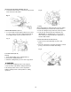
BODY AND HAND POSITION {FIG. P) • Never place hands near the cutting area. Proper positioning of your body and hands when operating the miter saw will make cutting easier and safer. Place hand at least 6-3/4 in. away from the path of the blade, out of the “No-Hands Zone.“ Hold workpiece firmly against the fence to prevent movement toward the blade. Before making a cut, with the power switch in the OFF position bring the saw blade down to the workpiece to see the cutting path of the blade.
BEVEL CUT (FIG. S) 1. When a bevel cut is required, loosen the bevel lock handle (1). 2. Tilt the cutting head to the desired angle as shown on the bevel scale (2). The blade can be positioned at any angle, from a 90° straight cut (0° on the scale) to a 45° left bevel. 3. Tighten the bevel lock handle (1) to lock the cutting head in position. CUTTING BOWED MATERIAL (FIG. U) A bowed workpiece must be positioned against the fence and secured with a clamping device before cutting.
WORKPIECE SUPPORT (FIG. V) Long pieces need extra support. The support should be placed under the workpiece. Keep your hand holding the workpiece positioned 6-3/4 inches or more away from the blade. The support must let the workpiece lay flat on the work table during the cutting operation. NOTE; When mounted on a flat surface, the miter saw table is 3-1/4 inches high. Fig. W r Fig. V Cutting capacity with auxiliary fence Crosscut 3-1/2 in. X 3-1/2 in. Miter 45° R & L 3-1/2 in. X 2 in. Bevel 45° L 2 in.
Fig. Z CUTTING A DIMENSIONAL 4X4 WITH ONE CUT (Fig. X) A dimensional 4x4 workpiece (3-1/2 in. x 3-1/2 in. ) may be cut in half with one cut by attaching an auxiliary wood fence of 3/4 inch thick. See “AUXILIARY WOOD FENCE” above. Fig. X NOTE: Always perform a dry run cut so you can determine if the operation being attempted is possible before power is applied to the saw. VERTICAL MITER CUTTING (FIG. Y) To make a miter cut in a 2x4 workpiece (1-1/2in. x 3-1/2in.
CUTTING CROWN MOLDING (FIG. AA,BB) Bevel/Miter Settings NOTE; The chart below references a compound cut for crown molding ONLY WHEN THE ANGLE BETWEEN THE WALLS EQUALS EXACTLY 90°. NOTE; The chart below references a compound cut for crown molding ONLY WHEN THE ANGLE BETWEEN THE WALLS EQUALS EXACTLY 90°. Your compound miter saw is suited for the difficult task of cutting crown molding. To fit properly, crown molding must be compound-mitered with extreme accuracy.
MAIMTENANC protection. Should the lower guard become damaged, do not use the saw until the damaged guard has been replaced. Develop a regular check to make sure the lower guard is working properly. Clean the lower guard of any dust or buildup with a damp cloth. MAINTENANCE A DANGER Never put lubricants on the blade while it is spinning. A WARNING CAUTION; Do not use solvents on the guard. They could make the plastic “cloudy” and brittle.
JJROUBLESHOOTING QUID A WARNING To avoid injury from accidental starting, always turn switch OFF and unplug the tool before moving, replacing the blade or making adjustments. Consult your Sears Service Centre if for any reason the motor will not run. TROUBLESHOOTING GUIDE - MOTOR PROBLEM Brake does not stop blade within 6 seconds. Motor does not start PROBLEM CAUSE SUGGESTED CORRECTIVE ACTION 1. Motor brushes not sealed or lightly sticking. 2.
PARTS LIS 10 in. COMPOUND MITER SAW MODEL NO. 137.212290 A WARNING When servicing use only CRAFTSMAN replacement parts. Use of any other parts many create a HAZARD or cause product damage. Any attempt to repair or replace electrical parts on this Miter Saw may create a HAZARD unless repair is done by a qualified service technician. Repair service is available at your nearest Sears Service Centre. To purchase replacement parts, call 1-800-469-4663. PARTS LIST FOR SAW SCHEMATIC l.D.
10 in. COMPOUND MITER SAW SCHEMATIC FOR SAW MODEL N0.137.
10 in. COMPOUND MITER SAW MODEL N0.137.212290 PARTS LIST AND SCHEMATIC FOR MOTOR I.D, NO Description Size OHVY BALL BEARING 6204ZZ 1 0HX9 NEEDLE BEARING HKOOlO 1 0JX3 HEX. SOC. SETSCREW M5*0.8-8 2 OKCN CR.RE.
I fi IJ Your Home For repair - in your home - of all major brand appliances, lawn and garden equipment, or heating and cooling systems, no matter who made it, no matter who sold it! For the replacement parts, accessories and Operator’s Manuals that you need to do-it-yourself. For Sears professional installation of home appliances and items like garage door openers and water heaters. 1-800-4-MY-HOME® (1 -800-469-4663) Call anytime, day or night (U.S.A. and Canada) www.sears.com sears.