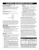
Operator's Manual CRFIFrSMAN° 10 in. COMPOUND MITER SAW AND STAND WITH LASER TRAC ® Model No. 137.212310 i CAUTION: Before using this Miter Saw, read this manual and follow all its Safety Rules and Operating Instructions Customer Help For Technical Support • • Operation Maintenance • Parts List Repair 1-800-843-1682 Parts Center 1-800-488-1222 Estates, IL 60179 USA Visit our Craftsman website: www.sears.com/craftsman Part No.
SECTION PAGE Warranty ............................................................. 2 Product Specifications ........................................ SECTION PAGE Carton Contents .................................................. 7 2 Know Your Compound Miter Saw ....................... 8 Power Tool Safety .............................................. Compound Miter Saw Safety .............................. 3 4 Glossary of Terms ...............................................
GENERAL BEFORE SAFETY INSTRUCTIONS USING THIS POWER TOOL Safety is a combination of common sense, staying alert and knowing how to use your power tool. WARNING J To avoid mistakes that could cause serious injury, do not plug the tool in until you have read and understood the following. READ and become familiar with the entire Operator's Manual. LEARN the tool's application, limitations and possible hazards. 2. KEEP GUARDS IN PLACE and in working order. 3 REMOVE ADJUSTING KEYS AND WRENCHES.
SPECIFIC SAFETY THIS COMPOUND INSTRUCTIONS FOR MITER SAW DO NOT USE THIN KERF BLADES they can deflect and contact guard and can cause possible injury to the operator. 2. 3. 4. 5. 6. 7. 8. 9. 18. MAKE SURE the blade is not contacting the workpiece before the switch is turned ON. 19. IMPORTANT: After completing the cut, release the trigger and wait for the blade to stop before returning the saw to the raised position.
ELECTRICAL REQUIREMENTS - cont'd DOUBLEINSULATED[] 4. The power tool is double insulated to provide a double thickness of insulation between you and tool's electrical system. All exposed metal parts are isolated from the internal metal motor components with protecting insulation. Replacement parts - When servicing, use only identical replacement parts. 5.
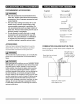
RECOMMENDED ACCESSORIES Supplied Not supplied I_ WARNING I • Use only accessories recommended for this miter saw. Follow instructions that accompany accessories. Use of improper accessories may cause hazards. • Blade Wrench Adjustable Wrench The use of any cutting tool except 10 in. saw Hex Key blades which meet the requirements under recommended accessories is prohibited. Do not use accessories such as shaper cutters or • dado sets.
UNPACKING YOUR MITER SAW 2. 3. IA WARNING I items are accounted for, before discarding any packing material. To avoid injury from unexpected starting or electrical shock, do not plug the power cord into a source of power during unpacking and assembly. This cord must remain unplugged whenever you are Place the saw on a secure stationary work surface. Separate all parts from the packing material. Check each one with the illustration to make certain all la, WARNING I working on the saw.
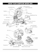
CuttingHeadHandle UpperBlade ON/OFFTriggerSwitch Cover DustBac Blade LowerBladeGuard LaserGuide htExtension Table BevelScale Hold-down Claml: PositiveStopLockingLever LeftExtension Table Handle Stop Base Laser On/Off Switch MiterScale Wrench Storage ArborLock Latch Table Pivot Bolt Table Lock Nut \ Mounting Hand Location for Transportation Positive Miter Detents Table Lock Knob
COMPOUND MITER SAW TERMS ARBOR LOCK - Allows the user to keep the blade from rotating while tightening or loosening the arbor bolt during blade replacement or removal. BASE - Supports the table, holds accessories and allows for workbench or leg set mounting. BEVEL LOCKING HANDLE - Locks the miter saw at a WRENCH STORAGE - Convenient storage to prevent misplacing the blade wrench. WOODWORKING TERMS ARBOR - The shaft on which a blade is mounted.
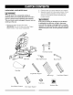
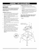
ASSEMBLY INSTRUCTIONS ASSEMBLE MITER SAW TO STAND 1,4 WARNING I 1. 2. To avoid injury, do not connect this miter saw to the power source until it is completely assembled and adjusted and you have read and understood this Carefully place the miter saw on top of stand. Line up the four mounting holes in the saw base to the stand. 3. Fasten the saw to the stand using the four mounting bolts (9), four washers (10) and four nuts (11 ). Operator's Manual.
INSTALLING THE MITER HANDLE (FIG. B) Fig, D 1. Thread the miter handle (1) into the hole (2) located at the front of the miter table. Fig, B t 1 Locking When transporting or storing the miter saw, the cutting SAW BLADE WRENCH (FIG. C) head should always be locked in the down position. 1. Push the cutting head (3) down to its lowest position. 2. Push the stop latch (2) into the locking hole (4). IMPORTANT: To avoid damage, never carry the 1.
REMOVING (FIG.F, G, G-l) 1. Unplugthesawfromtheoutlet. 2. Allowthemitersawto risetotheuprightposition. Raisethelowerbladeguard(1)totheupposition. (Fig.F) 3. Loosenthecoverplatescrew(2)witha Phillips screwdriver. 4. Rotatethecoverplate(3)towardstherearofthetool toexposethearborbolt(4). 5. Placethebladewrenchoverthearborbolt. Fig.F NOTE: Pay attention to the pieces removed, noting their position and direction they face. Wipe the blade collars clean of any sawdust before installing the new blade.
INSTALLING THE HOLD-DOWN CLAMP ASSEMBLY (FIG. H) Fig. I 2 1 1. Loosen the lock handle knob (3) from the rear side of the saw base (4). 2. Place the hold-down clamp assembly (1) in one of the mounting holes (2). 3. Tighten the knob. IAk WARNING I When clamp clamp cause using stop block on the right side, hold-down must also be in right side. Using hold-down on the left side during this operation can kickback and serious injury to the operator. MITER SCALE (FIG.
Fig. M Cutting head downward travel adjustment (Fig. L) IA. WARNING [ To avoid injury from unexpected starting or electrical shock, turn the switch OFF and remove the power cord from the power source. NOTE: Before each cutting operation, check the position of the blade to make sure it does not contact any metal surface. If the blade contacts any metal surface, the depth of travel must be adjusted. 1. Lower the blade as far as possible. 2. Loosen the Iocknut (3). 3.
MOUNTING THE MITER SAW (FIG. O) Stationary Use To avoid injury from unexpected saw movement: • Before moving the saw, disconnect the power cord from the outlet, and lock the cutting arm in the lower position using the stop latch. NOTE: The stop latch is for carrying or storing the tool. It is not to be used for holding the saw while cutting. Lower blade and press in stop latch to secure saw for transport or storage. • Never carry the miter saw by the power cord or by the switch handle.
ALIGNING THE LASER BEAM (FIG. P-l, P-2) screws (1). Start with the set screw on the left side of the laser assembly, then with the front set screw on the I_ WARNING I right side of the laser assembly. For your own safety, never connect the plug to power source outlet until all the adjustment steps are complete and you have read and understood the safety and operational instructions. Fig. P-1 The laser beam must always be correctly aligned with the blade to ensure straight, even cutting.
SAFETY INSTRUCTIONS OPERATION FOR BASIC SAW BEFORE USING THE MITER SAW • 1,4 WARNING I • To avoid mistakes that could cause serious, permanent injury, do not plug the tool in until the following steps are completed: • Completely assemble and adjust the saw, following the instructions. (ASSEMBLY AND ADJUSTMENTS) • Learn the use and function of the ON/OFF trigger switch, on/off switch for laser, upper and lower blade guards, stop latch, bevel lock handle, and cover plate screw.
PLANYOURWORK • Usetherighttool.Don'tforcea toolor attachment to doa jobit wasnotdesignedtodo.Usea different toolforanyworkpiece thatcan'tbeheldina solidly braced,fixedposition. • • • CAUTION: This machine is not designed for cutting masonry, masonry products, ferrous metals (steel, iron, and iron-based metals.) Use this miter saw to cut only wood, wood-like products, or non-ferrous metals. Other material may shatter, bind the blade, or create other dangers.
BODY AND HAND POSITION (FIG. Q) TURNING SAW ON (FIG. R) WARNING I * WARNING I Never place hands near the cutting area. Proper positioning of your body and hands when operating the miter saw will make cutting easier Make the switch child-proof. Insert a padlock through the hole (2) in the trigger switch and lock it. This will prevent children and other unauthorized users from engaging the trigger switch ON. and safer. Keep children away. Keep all visitors at a safe distance from the miter saw.
BEVEL CUT (FIG, T) 1. When a bevel cut is required, loosen the bevel lock handle (1). CUTTING BOWED MATERIAL (FIG. V) A bowed workpiece must be positioned against the fence and secured with a clamping device before cutting. Do not position workpiece incorrectly or try to cut the workpiece without the support of the fence. This 2. Tilt the cutting head to the desired angle as shown on the bevel scale (2).
WORKPIECE SUPPORT (FIG.W) Longpiecesneedextrasupport.Thesupportshouldbe placedundertheworkpiece. Keepyourhandholdingthe workpiecepositioned 6-3/4inchesor moreawayfrom theblade.Thesupportmustlettheworkpiece layflat ontheworktableduringthecuttingoperation. NOTE:Whenmountedona flatsurface,themitersaw tableis 3-1/4incheshigh. AUXlLARYWOODFENCE(FIG.
CUTTINGA DIMENSIONAL 4X4 WITH ONE CUT Fig. AA (FIG. Y) A dimensional 4x4 workpiece (3-1/2 in. x 3-1/2 in. ) may be cut in half with one cut by attaching an auxiliary wood fence of 3/4 inch thick. See "AUXILIARY WOOD FENCE" above P m F e n c Fig, Y Auxiliary Fence_ _ Miter Saw Table 3-1/2 in. Miter Saw Table miter at 45 °, bevel at 0° miter at 0°, bevel at 45 o Miter Saw Fence _ \ I 3-1/2 in.
CUTTING CROWNMOLDING (FIG.BB,CC) NOTE: The chart below references a compound cut for crown molding ONLY WHEN THE ANGLE BETWEEN THE WALLS EQUALS EXACTLY 90 °. Your compound miter saw is suited for the difficult task of cutting crown molding. To fit properly, crown molding must be compound-mitered with extreme accuracy. The two surfaces on a piece of crown molding that fit flat against the ceiling and wall are at angles that, when added together equal exactly 90 °.
protection. Should the lower guard become damaged, do not use the saw until the damaged guard has been replaced. Develop a regular check to make sure the lower guard is working properly. Clean the lower guard of any dust or buildup with a damp cloth. MAINTENANCE IA DANGER I To avoid injury, never put lubricants on the blade while it is spinning. la, WARNING I CAUTION: Do not use solvents on the guard. They could make the plastic "cloudy" and brittle.
IA WARNING I To avoid injury from accidental starting, always turn switch OFF and unplug the tool before moving, replacing the blade or making adjustments. TROUBLESHOOTING GUIDE - MOTOR PROBLEM PROBLEM CAUSE Brake does not SUGGESTED CORRECTIVE ACTION Motor brushes not sealed or lightly sticking. Motor brake overheated from use of stop blade within 6 seconds. defective or wrong size blade or rapid ON/OFF cycling. Arbor bolt loose. 4. 5. Brushes cracked, damaged, etc. Other. 2.
10 in. COMPOUND MITER SAW MODEL NO. 137.212310 WARNING I When servicing use only CRAFTSMAN replacement parts, Use of any other parts many create a HAZARD or cause product damage. Any attempt to repair or replace electrical parts on this Miter Saw may create a HAZARD unless repair is done by a qualified service technician. Repair service is available at your nearest Sears Service Center, PARTS LIST FOR SAW SCHEMATIC Size QTY QTY I.D. Description I.D.
10 in. COMPOUND MITER SAW MODEL NO. 137.212310 SCHEMATIC FOR SAW 0KU_ 2 OKA9 2COF OK_Ke 25TF OJAZ_ 2CS_0JMM _v/_OjTR OKRO 0JZN 2F3M / OKQX 2BPW OKDH 2DAS 0824 .
10 in. COMPOUND MITER SAW PARTS LIST AND SCHEMATIC MODEL NO. 137.212310 FOR MOTOR Size QTY I.D. Description 0HX9 NEEDLE BEARING 0JB8 WAVE WASHER 1 0JX3 HEX. SOC. SETSCREW 2 0KCN CR.RE.
10 in. COMPOUND MITER SAW MODEL NO. 137.212310 PARTS LIST AND SCHEMATIC FOR STAND QTY Size I.D. Description 093B FOOT PAD 0J4F FLAT WASHER q_8X] 6-2.5 0KE3 CR. RE. PAN HD. SCREW M8* ] .25-35 3 0KRR SERRATED TOOTHED HEXAGON FLANGE NUT M8* ] .25 T=7.5 ]9 20N0 FOOT PAD ASS'Y 22XY LEG #06 4 2A10 CAP HD. SQ.
Your Home For repair - in your home - of all major brand appliances, lawn and garden equipment, or heating and cooling systems, no matter who made it, no matter who sold it! For the replacement parts, accessories and owner's manuals that you need to do-it-yourself. For Sears professional installation of home appliances and items like garage door openers and water heaters. 1-800-4-MY-HOME Call anytime, ® (1-800-469-4663) day or night (U.S.A. and Canada) www.sears.oom www.sears.