Operator's Manual CRFIFrSMAN° 10 in. COMPOUND MITER SAW AND STAND WITH LASER TRAC ® Model No. 137.212520 CAUTION: Before using this Miter Saw, read this manual and follow all its Safety Rules and Operating Instructions Customer For Help Technical • • Operation Maintenance • Parts List Repair Support 1-800-843-1682 Parts Center 1-800-488-1222 Estates, IL 60179 USA Visit our Craftsman website: www.sears.com/craftsman Part No.
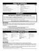
SECTION PAGE Warranty ............................................................. 2 Product Specifications ........................................ SECTION PAGE Carton Contents .................................................. 7 2 Know Your Compound Miter Saw ....................... 8 Power Tool Safety .............................................. Compound Miter Saw Safety .............................. 3 4 Glossary of Terms ...............................................
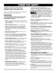
GENERAL BEFORE SAFETY INSTRUCTIONS USING THIS POWER TOOL Safety is a combination of common sense, staying alert and knowing how to use your power tool. WARNING J To avoid mistakes that could cause serious injury, do not plug the tool in until you have read and understood the following. 1. READ and become familiar with the entire Operator's Manual. LEARN the tool's application, limitations and possible hazards. 2. KEEP GUARDS IN PLACE and in working order. 3. REMOVE ADJUSTING KEYS AND WRENCHES.
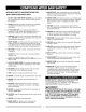
SPECIFIC SAFETY THIS COMPOUND INSTRUCTIONS FOR MITER SAW 1. DO NOT USE THIN KERF BLADES they can deflect and contact guard and can cause possible injury to the operator. 2. DO NOT operate the miter saw until it is completely assembled and installed according to these instructions. 3. IF YOU ARE NOT thoroughly familiar with the operation of miter saws, seek guidance from your supervisor, instructor or other qualified person. 4. ALWAYS hold the work firmly against the fence and table.
ELECTRICAL REQUIREMENTS - cont'd DOUBLEINSULATED[] 4. The power tool is double insulated to provide a double thickness of insulation between you and tool's electrical system. All exposed metal parts are isolated from the internal metal motor components with protecting insulation. Replacement parts - When servicing, use only identical replacement parts. 5.
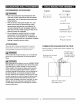
RECOMMENDED ACCESSORIES Supplied Not supplied WARNING I • Use only accessories recommended for this miter saw. Follow instructions that accompany accessories. Use of improper accessories may cause hazards. • Blade Wrench Adjustable Wrench The use of any cutting tool except 10 in. saw Hex Key 2.5 mm blades which meet the requirements under recommended accessories is prohibited. Do not use accessories such as shaper cutters or • dado sets.
UNPACKING YOUR MITER SAW 2. Place the saw on a secure stationary work surface. 3. Separate all parts from the packing material. Check each one with the illustration to make certain all items IA WARNING I are accounted for, before discarding any packing material. To avoid injury from unexpected starting or electrical shock, do not plug the power cord into a source of power during unpacking and assembly. This cord must remain unplugged whenever you are WARNING I working on the saw.
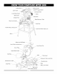
CuttingHead Switch Handle ON/OFF Trigger Switch LaserGuide ........ Carrying Handle LowerBladeGuard Motor BevelScale Stop Latch SlidingFence J Bevel Lock Handle Right Extension Table Stop Plate Positive Stop Locking Lever Quick-Cam Miter Table Lock Stand Safety Lock-Off Button Laser Guide Locking Lever Laser Guide Tab Cover Plate Upper Blade Guard _. Dust Bag Table iJ Table Insert --_Extension Table Lock Knob J Left Extension Table Mounting Hole \ Base Stop Plate Miter Lock Handle
COMPOUND MITER SAW TERMS ARBOR LOCK - Allows the user to keep the blade from rotating while tightening or loosening the arbor bolt during blade replacement or removal. BASE - Supports the table, holds accessories and allows for workbench or leg set mounting. BEVEL LOCKING HANDLE - Locks the miter saw at a WRENCH STORAGE - Convenient storage to prevent misplacing the blade wrench. WOODWORKING TERMS ARBOR - The shaft on which a blade is mounted.
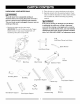
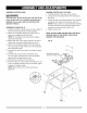
ASSEMBLY INSTRUCTIONS ASSEMBLE MITER SAW TO STAND 1,4 WARNING I 1. Carefully place the miter saw on top of stand. 2. Line up the four mounting holes in the saw base to the stand. To avoid injury, do not connect this miter saw to the power source until it is completely assembled and adjusted and you have read and understood this 3. Fasten the saw to the stand using the four mounting screws (9), four washers (10) and four nuts (11). Operator's Manual.
INSTALLING INSTALLING THE MITER HANDLE (FIG. B) 1. Thread the miter handle (1) into the hole (2) located at the front of the miter table. THE DUST COLLECTION ELBOW AND THE DUST BAG (FIG. E) 1. Install the larger end of the elbow (1) onto the exhaust port (2). NOTE: The elbow can be used to attach either the Fig. B dust bag or a vacuum hose to remove sawdust from the work area. Fig, E SAW BLADE WRENCH (FIG. C) 1.
6. Locate the arbor lock (5) on the motor, below the 3. Place the blade wrench on the arbor bolt. miter saw switch handle. (Fig. G) 7. Press the arbor lock, holding it in firmly while turning the blade wrench clockwise. The arbor lock will 4. Press the arbor lock (5), holding it in firmly while turning the blade wrench counterclockwise. When it engages, continue to press the arbor lock in, while tightening the arbor bolt securely. (Fig. G) engage after turning the wrench.
MOUNTING THE MITER SAW ONTO A WORK Fig. K SURFACE (FIG. J, K) WARNING I To avoid injury form unexpected saw movement: • Disconnect the power cord from the outlet, and lock the cutting head in the lower position using the lock pin. • Lock the slide carriage in place by tightening the slide carriage lock knob. • To avoid back injury, lift the saw by using the designated carrying handle located on the top of the machine. When lifting, bend at your knees, not from your back.
0 ° Bevel Pointer Adjustment (Fig. M) MITER ANGLE ADJUSTMENT 1. When the blade is exactly 90 ° (0 °) to the table, loosen the bevel indicator screw (5) using a # 2 Phillips screwdriver. 2. Adjust bevel indicator (6) to the "0" mark (7) on the The compound miter saw scale can be easily read showing miter angles from 0° to 45 ° to the left and right. The most common angle cut setting slots have positive stops, permitting fast adjustments to the desired position.
QUICK-CAM MITER TABLE LOCK ADJUSTMENT IA WARNING I (FIG. Q) 1. Press down and lock the miter quick-cam table lock. 2. Using a 13 mm wrench, turn the stop nut (4) to the left as shown to extend the locking arm against the base of the miter saw. To avoid injury from unexpected starting or electrical shock, do not plug the saw in. The power cord MUST remain unplugged when you are working on the saw. 3. Test the quick cam miter lock to verify it locks the table into position securely. Fig, P 4.
ALIGNING THE LASER BEAM B. Check Laser Beam Alignment. (FIG.T, T-1 & T-2) 1. Mark a straight line across a board to serve as a "pattern line" to test laser alignment. Lay the board on the miter table. IAk WARNING I For your own safety, never connect the plug to 2. Turn on the laser beam and line it up with the pattern line. power source outlet until all the adjustment steps are complete and you have read and understood the safety and operational instructions. 3.
Fig. T-2 Pattern Line Pattern Line Laser Line D. Aligning Parallelism (Fig. T-l, T-3 ) 1. Adjust screw screw screw laser line parallel to pattern line by turning (3) (Fig. T-1 ). NOTE: Do not overturn this or it may damage internal wiring. Maximum turn is 1/8 turn in each direction. 2. Move laser close to pattern line by turning screw (4). 3. Fine tune alignment of laser is achieved by adjusting screw (4) no more than 1/8 turn in each direction. Fig.
SAFETY INSTRUCTIONS OPERATION FOR BASIC SAW • Replace bent, damaged, missing or defective parts before using the saw again. • Maintain tools with care. Keep the miter saw clean for best and safest performance. Follow instructions for lubricating. Don't put lubricants on the blade while it's spinning. • Remove adjusting wrench from the tool before turning it on. • To avoid injury from jams, slips, or thrown pieces, use only recommended accessories.
PLANYOURWORK • Usethe righttool.Don'tforcea toolor attachment todoa jobit wasnotdesignedto do.Usea different toolforanyworkpiece thatcan'tbeheldina solidly braced,fixedposition. • Keep the cut off piece free to move sideways after it is cut off. Otherwise, it could get wedged against the blade and thrown violently. • Only the workpiece should be on the saws table. • Secure work. Use clamps or a vise to help hold the work when it's practical.
BODY AND HAND POSITION (FIG. W) WARNING I Never place hands near the cutting area. Proper positioning of your body and hands when operating the miter saw will make cutting easier and safer. Keep children away. Keep all visitors at a safe distance from the miter saw. Make sure bystanders are clear of the saw and workpiece. Don't force the saw. It will do the job better and safer at its designed rate. Starting a cut: • Place hands at least 6-3/4 in.
SLIDINGFENCE(FIG.Y) snaps into place. NOTE: The lever will only lock into I_WARNING 4. The sliding fence must be extended when making any bevel cut, Failure to extend the sliding fence will not allow enough space for the blade to pass through which could result in serious injury. At extreme miter or bevel angles the saw blade may also contact the fence. 5. place at one of the nine positive stops.
WORKPIECE SUPPORT & REPETITIVE CUTTING USINGTHESTOPPLATE(FIG.EE) Longpiecesneedextension table support. COMPOUND CUT(FIG.CC) 1. Extendtheslidingfenceasdescribed in SLIDING FENCE(Fig.Y). 2. Setthedesiredbevelangleusingthebevellock handle(1). 3. Setthedesiredmiterangleandlockintoposition. See"MITERCUT". 1. Loosen the knob (1) then slide the extension wing to desired position and tighten the knob. 2. The stop plate is designed for use during repetitive cutting. Only use one stop plate at a time.
CUTTINGBASEMOLDING (FIG,GG) Basemoldingsandmanyothermoldingscanbecuton a compound mitersaw.Thesetupofthesawdepends on moldingcharacteristics andapplication, asshown. Performpracticecutson scrapmaterialtoachievebest results: 1. Alwaysmakesuremoldingsrestfirmlyagainstfence andtable.Usehold-down, crownmoldingviseor C-clamps, wheneverpossibleandplacetapeonthe areabeingclampedto avoidmarks. 2. Reducesplinteringbytapingthecutareapriorto makingthecut.Markthecutlinedirectlyonthetape. 3.
INSTALLING / CHANGING • Unplug your saw. IA WARNING I Failure to unplug your saw could result in accidental starting causing possible serious personal injury. 1. Flip laser guide locking lever to left. 2. Use laser guide tab to pull out laser guide. 3. Lift open the battery guide cover (1). 4. Install two batteries with 1.5 volt AAA size. NOTE: When replacing the batteries, the battery guide should be thoroughly cleaned. Use a soft paintbrush or similar device, to remove any sawdust and debris. Fig.
MAINTENANCE IA LOWER BLADE DANGER I To avoid injury, never put lubricants on the blade while it is spinning. I_ WARNING I To avoid fire or toxic reaction, never use gasoline, naphtha acetone, lacquer thinner or similar highly volatile solvents to clean the miter saw. IA WARNING I To avoid injury from unexpected starting or electrical shock, unplug the power cord before working on the saw. IA WARNING i For your safety, this saw is double-insulated.
IA WARNING I To avoid injury from accidental starting, always turn switch OFF and unplug the tool before moving, replacing the blade or making adjustments. TROUBLESHOOTING PROBLEM Brake does not stop blade within 6 seconds• GUIDE - MOTOR PROBLEM CAUSE SUGGESTED CORRECTIVE ACTION • Motor brushes not sealed or lightly sticking. 2. Motor brake overheated from use of defective or wrong size blade or rapid Inspect/clean/replace brushes• See MAINTENANCE section. 2. Use a recommended blade. Let cool down.
10 in. COMPOUND MITER SAW MODEL NO. 137.212520 I A WARNING I When servicing use only CRAFTSMAN replacement parts. Use of any other parts many create a HAZARD or cause product damage, Any attempt to repair or replace electrical parts on this Miter Saw may create a HAZARD unless repair is done by a qualified service technician. Repair service is available at your nearest Sears Service Center. PARTS LIST FOR SAW SCHEMATIC I.D.
10 in. COMPOUND MITER SAW MODEL NO. 137.212520 SCHEMATIC FOR SAW .OKBC4 083Y 085X 084_ b_ 084M .
10 in. COMPOUND MITER SAW PARTS LIST AND SCHEMATIC MODEL NO. 137.212520 FOR MOTOR I.D. 1100 1102 0HV8 0HVU 0HX9 0gX2 0K56 0KCM 0KLA 0KWM 0PLT 0Q9K 0QGR 0QME 0QMK 0QMR 0QMY 0QMZ 0QQS 0QQT 0QR0 Description GEAR BOX COVER SPRING PIN BALL BEARING BALL BEARING NEEDLE BEARING HEX.-SOC SETSCREW CR. RE. COUNT HD. SCREW CR.-RE.PAN HD. AP.
10 in. COMPOUND MITER SAW MODEL NO. 137.212520 PARTS LIST AND SCHEMATIC FOR STAND I.D. 093B 0J4F 0KE3 0KRR 0STZ 2A10 2E19 2E1A 2E1B 2E1C 2E1D Description FOOT PAD FLAT WASHER CR. RE. PAN HD. SCREW SERRATED TOOTHED HEXAGON TRADE-MARK LABEL CAP HD. S©.NECK BOLT BOTTOM SUPPORT BRACKET BOTTOM SUPPORT BRACKET UPPER SUPPORT UPPER SUPPORT BRACKET Size 8 * 16-2.5 M8* 1.25-35 M8* 1.25 T=7.5 FLANGE NUT M8"0.25-12 0KE34 0J4F4 2E1B2\ 2E1C2 2A10/6 0KRR2o 0STZ 2E192 2EIA2 2E1 D4 093B4 J QTY 4 4 4 20 1
Your Home For repair - in your home - of all major brand appliances, lawn and garden equipment, or heating and cooling systems, no matter who made it, no matter who sold it! For the replacement parts, accessories and owner's manuals that you need to do-it-yourself. For Sears professional installation of home appliances and items like garage door openers and water heaters. 1-800-4-MY-HOME Call anytime, ® (1-800-469-4663) day or night (U.S.A. and Canada) www.sears.oom www.sears.