Operator's Manual ® 10 in. DRILL PRESS With Laser Trac ® Model No. 137.219001 CAUTION: e e e e e Before using this Drill Press, read this manual and follow all its Safety Rules and Operating Instructions Customer Help 1-800-843-1682 Safety Instructions Installation Operation Maintenance Parts List Line Sears Brands Management Corporation Hoffman Estates, See the full line of Craftsman ® products at craftsman.com Click on the Craftsman Club ®link and join today! Part No. 137.
SECTION PAGE Warranty ................................................... Product Specifications .............................. Safety Guidelines - Definition ................... Power Tool Safety ..................................... Drill Press Safety ...................................... Electrical Requirements And Safety .......... Accessories And Attachments ................... Tools Needed For Assembly ..................... Carton Contents ........................................
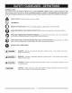
WARNING iCONS Your power tool and its Operator's Manual may contain "WARNING iCONS" (a picture symbol intended to alert you to and/or instruct you how to avoid a potentially hazardous condition). Understanding and heeding these symbols will help you operate your tool better and safer. Shown below are some of the symbols you may see. A SAFETY ALERT: Precautions that involve your safety.
10. USE PROPER EXTENSION CORDS. Make sure GENERAL SAFETY INSTRUCTIONS BEFORE USING THIS POWER TOOL your extension cord is in good condition. When using an extension cord, be sure to use one heavy enough to carry the current your product will draw. An undersized cord will result in a drop in line voltage and in loss of power which will cause the tool to overheat. The table on page 8 shows the correct size to use depending on cord length and nameplate ampere rating. If in doubt, use the next heavier gauge.
17.USERECOMMENDED ACCESSORIES. ConsultthisInstruction Manualforrecommended accessories. Theuseof improperaccessories may causeriskof injurytoyourselfor others, 18.NEVERSTANDONTHETOOL.Seriousinjury couldoccurifthetoolis tippedor ifthecuttingtoolis unintentionally contacted, 21.DONOTOVERREACH. Keepproperfootingand balanceatalltimes. 22.MAINTAIN TOOLS WITH CARE. Keep tools sharp and clean for best and safest performance. Follow instructions for lubricating and changing accessories. 23.
l,&WAR.I.G ] For your own safety, do not try to use your drill press or plug it in until it is completely assembled and installed according to the instructions, and until you have read and understood this instruction manual: . CLAMP THE WORKPIECE OR BRACE IT against the left side of the column to prevent rotation. If it is too short or the table is tilted, clamp it solidly to the table and use the fence provided. 13.
23.WHENDRILLINGlargediameterholes,clampthe workpiece firmlytothetable.Otherwise, thebitmay grapandspintheworkpiece athighspeeds.DO NOTUSEflycuttersor multiple-part holecutters,as theycancomeapartor becomeunbalanced in use. 29. Drum sanders must never be operated on this drill press at a speed greater than the speed rating of the drum sander. 30. Feed workpiece into a sanding drum or other 24.MAKE SURE the spindle has come to a complete stop before touching the workpiece. 25.
GROUNDINGINSTRUCTIONS INTHE EVENT OF A MALFUNCTION OR (When using 120 volts only) BREAKDOWN, grounding provides a path of least resistance for electric current and reduces the risk of Ampere more than shock. This tool is equipped with an electric cord that has an equipment grounding conductor and grounding plug. The plug MUST be plugged into a matching receptacle that is properly installed and grounded in accordance with ALL local codes and ordinances. Rating not more than 25ft.
RECOMMENDED [,_WARNING ACCESSORIES UNPACKING AND CHECKING CONTENTS ,&WARNING I J Use only accessories recommend for this drill press. Ifany partismissingor damaged, do notplugthedrill Follow instructions that accompany accessories, Use of improper accessories may cause hazards, press inuntil themissingor damaged partisreplaced, and assembly iscomplete.
UNPACKING AND CHECKING CONTENTS A C D E J H G O N L P Q $ R
Depthstopnuts Beltspeedsightwindow Depthscalepointer Spindle pulley Motor pulley Depth scale Quillreturn coil/ spring Feed handle Spindle Rack ring _ Table bracket Table lock handle Pulley cover Belt speed sight window Bevel lock bolt Chuck key holder ", Base ON/OFF switch with Belt tension lock knob safety key Fence endstop Laser guide Head locking screw Chuck Bevel scale Table crank handle Table Column Rack Mounting holes 11
BASE- Supportsdrillpress.Foradditionalstability, holesareprovidedinbaseto boltdrillpressto workbench. HEADLOCKING SCREWS - Lockstheheadtothe column.ALWAYSlockheadin placewhileoperatingthe drillpress. BACKUPMATERIAL - A pieceofscrapwoodplaced betweentheworkpieceandtable.Thebackupboard prevents woodintheworkpiece fromsplintering when thedrillpassesthroughthebacksideoftheworkpiece.It alsopreventsdrillingintothetabletop.
ASSEMBLY INSTRUCTIONS Fig. B [ WARNING I Foryourown safety, never connectplugtopower sourceoutletuntil allassemblystepsarecompleteand you have read and understoodthesafetyand operating instructions. 1 3 [,AWARNING I The drill pressisa heavy power tooland shouldbe lifted withthehelpoftwo PEOPLE OR MORE tosafely assemble it, ASSEMBLING COLUMN TO BASE (FIG. A) 1. Position the base (2) on a flat, stable worksurface (must be able to support 100 Ibs.). 2.
, Slide this table assembly with the rack onto the column. Fig. F 5. Engage the bottom of the rack (5) with the lip of the column support (6). Tighten the table bracket lock 10 handle (4) to lock the table assembly to the column, NOTE: Do not overtighten. ® © 11 12 _5 INSTALLING THE HEAD (FIG. G) wAR.I.G t , The Drill Press head is heavy and should be lifted with the help of two PEOPLE to safely assemble the drill press head on the column.
iNSTALLiNG THE CHUCK (FIG. I, J AND K) I,A [,_WARNiNG RISK OF PROPERTY DAMAGE. To avoid damage to the chuck, NEVER drive the chuck on the spindle with a metal hammer. ] Before any assembly or the chuck to the drill press head, clean all mating surfaces with a non-petroleum based product. Any oil or grease used in the packing of these parts must be removed otherwise the chuck may come loose during operation. ,_WARNING CAUTION] Fig.
CHUCKKEYSTORAGE (FIG.M) To protect the drill press from moisture, a protective coating has been applied to the machined surfaces. Remove this coating with a soft cloth moistened with kerosene or WD-40. Storage holder (1) for the chuck key (2) is located on the right side of the drill press, Fig. M ADJUSTMENT INSTRUCTIONS NOTE: All the adjustments for the operation of the drill press have been completed at the factory. Due to normal wear and use, some occasional readjustments may be necessary.
[,AWARNING l NOTE: DO NOT OVERTIGHTEN movement. and restrict quill To prevent personal injury, always disconnect the plug from the power source when making any adjustments. SPINDLE / QUILL (FIG. P) Rotate the feed handles counterclockwise to lower spindle to its lowest position. Hold the chuck and move it front to back. If there is excessive play, proceed with Fig. Q _4 the following adjustments: 1. Loosen the lock nut (1) located on the right side of the drill press, using a 10 mm wrench. 2.
[ WAR"ING 1 ,_WARNING AVOID DIRECT EYE CONTACT LASER RADIATION. Never aim the beam at a work piece with a reflective surface. Bright shiny reflective sheet steel or similar reflective surfaces are not recommended for laser use. Reflective surfaces could direct the beam back toward the operator or by standers. A Laser light is radiated when the laser guide is turned on. Avoid direct eye contact. Always un-plug the drill press from the power source before making any adjustments.
BASIC DRILL PRESS OPERATIONS ,AWARNING ALWAYS lock the switch "OFF" when the drill press is not in use by removing the safety switch key keep it in a NOTE: This machine incorporates view windows on the pulley cover used to observe the location of the belt. [_WARNING I safe place.
USINGTHEFENCE(FIG.W) Thefenceprovidesa wayofaccuratelyandquickly settinguptheworkpiece forprecision or forrepetitive drillingoperations. 1. Usinga centerpunch or sharpnail,makean indentation intheworkpiece whereyouwantto drill. 2. Alignthelaserlines(x)withthe indentation onthe workpiece. 3. Loosentheknobs(1)andslidethefencebackstop(2) firmlyagainstthe longsideoftheworkpiece. Tighten theknobswhenin position. 4.
BASICOPERATING INSTRUCTIONS Togetthebestresultsandminimizethelikelihood of personalinjury,followtheseinstructions foroperating yourdrillpress. j. the panel on the inside pulley cover or the chart below for drilling speed information. For accessories, refer to the instructions provided with each accessory. [ WARNING I For your own safety, always read the SAFETY INSTRUCTIONS listed within this operator's manual. 4.
POSiTiONiNG THETABLEANDWORKPIECE (FIG.AA AND BB) 2. Turn the laser "ON" and align the laser lines (x) with 1. Lock the table (1) to the column (2) at a position so the tip of the drill bit (3) is just above the top of the TILTING THE TABLE (FIG. CC) the indentation before turning the drill ON. NOTE: The table arm and support (1) has a predrilled hole with a locking pin inserted for locking the table into workpiece (4). 2. ALWAYS place a BACK-UP MATERIAL (scrap wood) on the table beneath the workpiece.
,_ WARNING Fig. DD 1 For your own safety, turn the switch OFF and remove the plug from the power source outlet before maintaining or lubricating your drill press. Frequently blow out, using an air compressor or dust vacuum, any sawdust or metal chips that accumulates inside the motor, pulley housing, table and work surface. Always wear protective safety goggles.
[_WARNINGI To avoidinjury from accidental starting, alwaysturnswitchOFF and unplugthetoolbeforemoving,or making adjustments. • ConsultyourSears ServiceCenterifforany reasonthemotor willnotrun. PROBLEM Noisy operation Drill bit burn. POSSIBLE CAUSES REMEDY 1, Incorrect belt tension, 1. Adjust tension. See section "ASSEMBLYTENSIONING BELT" 2. Dry spindle. 3. Loose spindle pulley. 2. Lubricate spindle. See Section "LUBRICATION". 3. Check tightenness of retaining nut on pulley, and 4.
10 in. DRILL PRESS MODEL NO. 137.219001 WAR.I.G J When servicing use only CRAFTSMAN cause product damage. replacement parts. Use of any other parts many create a HAZARD or WAR.I.G J Any attempt to repair or replace electrical parts on this Drill Press may create a HAZARD unless repair is done by a qualified service technician. Repair service is available at your nearest Sears Service Center. PARTS LiST FOR SAW SCHEMATIC QTY No. I.D. No. Des€rip}ion No. I.D. No.
10 in. DRILL PRESS MODEL NO. 137.219001 SCHEMATIC 114 16 D [ [ ...... C [ // [ \ 29 \\'26 49 50 51 116 //83 84 H 85 58 ,\ ? /.
Congratulations on making a smart purchase. Your new Craftsman ® product is designed and manufactured for years of dependable operation. But like all products, it may require repair from time to time. That's when having a Repair Protection Agreement can save you money and aggravation.
Your Home For expert troubleshooting and home solutions advice: www.managemyhome.com For repair - in your home - of all major brand appliances, lawn and garden equipment, or heating and cooling systems, no matter who made it, no matter who sold it! For the replacement parts, accessories and owner's manuals that you need to do-it-yourself. For Sears professional installation of home appliances and items like garage door openers and water heaters.