
Operator`s manual


ASSEMBLY INSTRUCTIONS Fig. B
[ WARNINGI
Foryourown safety,neverconnectplugtopower
sourceoutletuntilallassemblystepsarecompleteand
you have read and understoodthesafetyand operating
instructions.
[,AWARNINGI
The drillpressisa heavy power tooland shouldbe
liftedwiththehelpoftwo PEOPLE OR MORE tosafely
assemble it,
ASSEMBLING COLUMN TO BASE (FIG. A)
1. Position the base (2) on a flat, stable worksurface
(must be able to support 100 Ibs.).
2. Place the column (1) on the base, aligning the three
mounting holes to the base.
3. Locate the three hex bolts (3) from the loose parts
bag.
4. Place a bolt in each hole through the column support
and thread into the base. Tighten with a 12 mm
wrench.
1
3
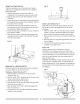
NOTE: Table removed from bracket in illustration for
clarity.
,
Place the rack (5)inside the table bracket (3) as
shown in Fig. C, making sure the worm gear (1) on
the inside of the table bracket is engaged with the
teeth of the rack and the arrow stamped on the
rack is pointing up.
Fig. A
3
Fig. C
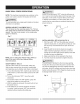
INSTALLING TABLE TO COLUMN ASSEMBLY
(FIG. B THROUGH F)
1. Install the table lock handle (4) into the hole
at the rear of the table bracket. NOTE: install
the handle from left to right, so it enters the
non-threaded side of the table bracket first.
2. insert the worm gear (1) into the table crank handle
hole (2) from inside the table support (3). Make sure
the worm gear (1) meshes with the inside gear.
NOTE: Do not remove the lubrication from this worm
gear.
13