
Operator`s manual


iNSTALLiNG THE CHUCK (FIG. I, J AND K)
[,_WARNiNG ]
Beforeany assembly or the chuckto the drill press head,
clean all mating surfaceswith a non-petroleum based
product. Any oil or grease used in the packing ofthese
parts must be removed otherwise the chuckmay come
looseduring operation.
,_WARNING 1
To avoid injury from an accidental start, ALWAYS make
sure the power switch is in the "OFF" position, the
switch key is removed, and the plug is not connected to
the power source outlet before removing or installing
the chuck.
.
.
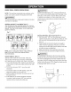
Clean out the tapered hole in the chuck (1) with a
clean cloth and a non-alcohol based cleaner. Wipe
clean all oil reside and any dirt or grime thoroughly.
Clean tapered surfaces on the spindle (2)in the
same manner as above.
NOTE: Make sure there are no foreign particles
sticking to the surfaces. The slightest piece of dirt or
oil reside on any of these surfaces will prevent the
chuck from seating properly. This will cause the drill
chuck and bit to wobble.
Fig. I
I,A CAUTION]
RISK OF PROPERTY DAMAGE. To avoid damage to
the chuck, NEVER drive the chuck on the spindle with
a metal hammer.
Fig. K
REMOVING THE CHUCK
1. Turn the feed handles to lower the chuck to the
lowest position.
2. Place a ball joint separator (not shown) above the
chuck and tap it lightly with a hammer or rubber
mallet to cause the chuck to drop from the spindle.
NOTE: Never hit the chuck directly with the hammer
or rubber mallet.
NOTE: The avoid possible damage to the chuck, raise
the jaws all the way first and be prepared to catch the
chuck as it falls.
.
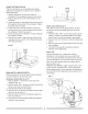
2
Open the jaws of the chuck (1) by rotating the chuck
sleeve clockwise. To prevent damage, make sure the
jaws are completely receded into the chuck.
Fig. J
2
1
4. Unlock the table support lock (4- Fig. D) and swing
the table away from the bottom of the chuck.
5. Insert the chuck onto the spindle, pushing upwards
all the way.
6. Using a rubber mallet or a hammer and a block of
wood, tap the chuck onto the spindle firmly (Fig. K).
MOUNTING DRILL PRESS TO WORK SURFACE
(FIG. L)
1. If mounting the drill press to a workbench, a solid
wood bench is preferred over a plywood board, to
reduce noise and vibration.
2. Holes should be pre-drilled through the supporting
surface.
3. The hardware to mount this drill press is NOT
supplied with the tool. The hardware as shown in the
illustration should be used:
Fig. L
1. Drill press base 4. Rubber washer 7. Lockwasher
2. Bolt 5. Worksurface 8. Hex nut
3. Flat washer 6. Flatwasher 9. Jam nut
_6 "
i i
_E
i i
__ I!
_E
E E
I!
/1
15