
Owner`s manual
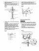
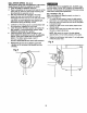
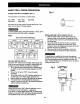
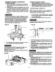

FENCE ASSEMBLY (RG, M)
1. Determine the desired location for the fence (1).
2. Align the mounting holesof the fence over the table
top slots. '
3. Place a washer (2) on the threaded end ofthe knob(3).
Insertthe knobthrough the mountinghole of the fence
and the table slot.
4. Place a washer and winGnut (4) on the knob from
under the table.
5. Repeat for the other knob and tighten.
V_rI_,_{_I_ [e
Fig. M
ADJUSTMENT INSTRUCTIONS
CAUTION: All the adjustments for the operation of the
drill press have been completed at the factory. Due to
normal wear and use, some occasional readjustments
may be necessary.
To avoid injuryfrom an accidental start, ALWAYS make
sure the sw_tch is in the "OFF" position, the switch key is
removed, and the plug is not connected to the power
source outlet before making belt adjustments.
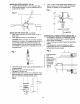
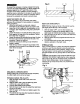
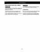
ALIGNING THE BELT PULLEYS (FIG. N)
Open the head cover of the Drill Press. Check alignment
of the pulleys with a straight edge (5) such as a framing
square, a level, or a piece of wood, Lay the straight edge
across the top of the pulleys. If all three pulleys are NOT
aligned:
1.. Release belt pressure by loosening the belt tension
lock knobs (2) on either side of the head,
counterclockwise.
2. Loosen the motor mount nuts (3). Lift or lower the
motor (4) until the pulleys are in line.
3. Tighten the motor mount nuts (3) using an adjustable
wrench.
4.
5.
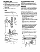
NOTE: To avoid rattles or other noise, the motor
housing should not touch the lower belt guard
housing.
Retighten the belt by pulling the motor (4) toward or
away from the drill press head, until the belt deflects
approximately 1/2 inch when pressed in the center.
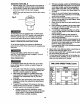
NOTE: Refer to the chart inside the belt guard
cover for recommended ddlling speeds and
belt / pulley positions.
Lock the belt tension lock knobs (2) by turning
clockwise.
NOTE: When the belt is new, it may be difficultto
move the belt, As the machine is used, the belt will
gain more elasticity and will be easier to adjust.
Fig. N
13