
Instruction Manual


5.
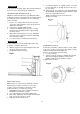
Slide the table support assembly with the rack (1,3,5)
together onto the column.
Engage the bottom of the rack (5) with the lip of the
column support (6). Tighten the support lock
handle (4) to lock the table support assembly to the
column.
4
3
9-
install the table crank handle (9) to the worm gear
shaft (1) on the side of the table support (6).
Line up the flat side of the shaft with the set screw (10)
in the crank handle and tighten the screw with a hex
wrench.
Fig. F
7. instali the collar (7) to the top end of the rack (5) on
the column.
IMPORTANT: The bottom of the collar MUST NOT
be pushed all the way down onto the top of the
rack. MAKE SURE the top of the rack is under
the bottom of the collar and that there is enough
clearance to allow the rack to freely rotate around
the column. Tighten the set screw (8).
CAUTION: To avoid column or collar damage, DO
NOT OVERTIGHTEN the set screw.
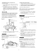
INSTALLING THE HEAD (FIG. G)
A WARNING
The Drill Press is very heavy and MUST be lifted with
the help of 2 PEOPLE OR MORE,, to safely assemble it.
1 Carefully lift head'(1) above the column (2) and slide
it onto the column. Make sure the head slides down
over the column as far as possible. Align the head
with the base.
2. Using the hex wrench, tighten the two head
lock set screws (3) on the right side of the head.
Fig.E
Fig.G
•7
5
11