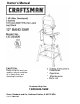
Owner’s Manual Before using this band saw, read this manual and follow all its Safety Rules and Operating Instructions. * Installation * Operation * Maintenance « Parts List Customer Help Line 1-800-843-1682 Sears, Roebuck and Co., Hoffman Estates, IL 60179 USA Part No.
TABLE OF CONTENT SECTION page Warranty................ ....................................................... ..................................................... .. ................ 2 Product Specifications ............................................................................................................................ 2 Safety Instructions................................................................................................................................
GENERAL SAFETY INSTRUCTIONS ALWAYS WEAR EYE PROTECTION. Any band saw can throw foreign objects into the eyes which could cause permanent eye damage. ALWAYS wear Safety Goggles (not glasses) that comply with ANSI safety standard Z87.1. Everyday eyeglasses have only impact-resistant lenses. They ARE NOT safety glasses. Safety Goggles are available at Sears. NOTE: Glasses or goggles not in compliance with ANSI Z87.1 could seriously hurt you when they break.
24. DO NOT operate the tool if you are under the influence of any drugs, alcohol or medication that could affect your ability to use the tool properly. 25. operate the band saw in a well-ventilated area and provide for proper dust removal. Use dust collection systems whenever possible. Dust generated from certain materials can be hazardous to your health. ALWAYS SPECIFIC SAFETY INSTRUCTIONS 1.
ELECTRICAL REQUIREMENTS POWER SUPPLY AND MOTOR SPECIFICATIONS A WARNING To avoid electrical hazards, fire hazards, or damage to the tool, use proper circuit protection. Use a separate electrical. circuit for your tools, Your saw is wired at the factory for 120V operation. Connect to a 120V, 15 Amp circuit and use a 15 Amp time delay fuse or circuit breaker. To avoid shock or fire, If power cord is worn or cut, or damaged in any way, have it replaced immediately.
Be sure your extension cord is properly wired and in good condition. Always replace a damaged extension cord or have it repaired by a qualified person before using it. Protect your extension cords from sharp objects, excessive heat and HH CARTON CONTENT UNPACKING AND CHECKING damp or wet areas. CONTENTS MINIMUM GAUGE FOR EXTENSION CORDS (AWQ) Carefully unpack the band saw and all its parts, and compare against the list below and the illustration on page 7.
UNPACKING YOUR BAND SAW D CC^tO O’er I] -V ^ J M o P
KNOW YOUR BAND
GLOSSARY OF TERMS CRAFTSMAN BAND SAW TERMS BLADE GUIDES ~ Support the blade and keep it from twisting during operation. Blade guides must be adjusted when the blade is changed or replaced. KERF - The material removed by a blade In a through cut, or the slot produced by the blade in a non-through or partial cut. LEADING EDGE - The end of the workpiece pushed into the cutting tool first. BLADE TENSION KNOB - Controls the amount of blade tension when changing blades.
ASSEMBLY AND ADJUSTMENTS ASSEMBLY INSTRUCTIONS A WARNING Although compact, this saw is heavy. To avoid back injury, get help to lift the saw. TOOLS NEEDED «ED ^ i ‘ r* I ‘ I ' i ' I l-A I iJ Combination square Phillips screwdriver I' I' p T“* I ■I II. i' II .'I'' I', I , 1' I . t ,'l ,-TrTT I I I Straight edge • Adjustable wrench Feeler gauge - size 0.02 ASSEMBLE BAND SAW TO LEG STAND (FIG. B) 1.
ASSEMBLE THE BAND SAW TABLE (FIG. D, E, F, G) 9. Turn the table right side up. 10. Remove the table insert (13) from the table, 11. Guide the table slot (14) over the saw blade and rotate a 1/4 turn, so the slot is perpendicular to the blade. 12. Placing the scale lock knob bolts (10) through the trunnion bracket holes (15) as shown, lower the table onto the trunnion bracket. Mounting the trunnion support bracket (FIG. D) 1. 2. 3. 4.
INSTALLING AND REMOVING BLADES (FIG. H) A WARNING To avoid injury from accidental starting, always turn the switch OFF and remove the plug from the power source before moving, replacing, or adjusting the blade. Installing 1. Make sure the blade tension knob (1) is turned counterclockwise until it stops. 2. Remove old blade as explained in “Removing”. 3. Guide the new blade (7) through the table slot (11). Make sure the blade teeth are pointing forward and down. Removing 1. 2. 3. 4. 5. 6. 7.
INSTALL POWER CORD BRACKETS (FIG. J) Adjusting th© 90° table stop (FIG. L) 1. 1. Power cord brackets (1) are provided for convenient cord storage. Attach the power cord brackets to the back of the saw body, as shown, with two Phillips head screws (2), Tighten. 2. Wrap the power cord onto the brackets when the band . saw is not in use, to prevent damage to the cord. 3. 4. FIG. J 7. 8. 9.
BLADE TENSiON (FIG. M) 5, A WARNING To avoid injury, turn the switch OFF and disconnect the saw from the power source before making any adjustments, NEVER make tension adjustments with the machine running. The gauge (1) on the bracket (2) at the rear of the upper wheel housing indicates the proper tension for the various blade widths, 1. 2. 3. If the blade moves toward the front of the wheel, turn the tracking knob (5) on the rear of the band saw clockwise.
UPPER BLADE GUIDES AMD BLADE SUPPORT BEARING (FIG. P, Q) ® The blade guard has been removed for clarity of illustration. To avoid injury never operate the band saw without all guards in place and in working order. * To avoid injury, turn the switch OFF and disconnect the saw from the power source before making any adjustments, NEVER make adjustments with the machine running. NOTE: Make sure the blade is tensioned and tracking properly.
Support bearing (FIG. S) 6. 7. 8. Loosen the bearing hex socket screw (7) with the hex wrench. Move the blade support bearing shaft (8) in or out until the support bearing (9) is 1/64" behind the saw blade. Tighten the bearing hex socket screw. OPERATION BASIC SAW OPERATIONS ON / OFF SWITCH (FIG. U) The keyed switch is intended to prevent unauthorized use of the band saw. 1. To turn the band saw ON insert the yellow key (1) into the key slot (2) in the center of the switch. 2.
To avoid twisting the blade, do not turn sharp corners, saw around corners. BLADE SELECTION (FIG. W) CAUTION: Blade teeth are sharp. Use care when handling a saw blade. A band saw Is basically a "curve-cutting" saw. It is not capable of doing intricate inside cutting as can be done with a scroll saw. For longest wear and best cutting results, use the correct blade thickness, width, and temper for the type of material you will cut.
CHANGING SPEED SETTING (FIG.Y) MAINTENANC A WARNING To avoid injury, turn the switch OFF and disconnect the saw from the power source before making any adjustments. NEVER make adjustments with the machine running. 1. Loosen the belt tension by turning the tension lock handle (6). 2. Open the lower wheel cover and reposition the V-belt (3). A, Changing the speed from 1410 to 2600 FPM: Remove the belt (3) from the band saw pulley (4) first, and reposition in the saw pulley groove (1).
12. Replace the blade wheel. Push the wheel on firmly until it is touching the saw pulley. Replace and tighten the flange and nut. 13. Reinstall the blade (See INSTALLING BLADES Section on page). 14. Adjust the blade tension, tracking, and the upper and lower blade guides and bearings before operating the band saw. BLADE WHEEL TIRES Pitch and sawdust that build up on the tires should be removed with a stiff brush or scrape off with a piece of wood.
TROUBLESHOOTING TROUBLESHOOTING GUIDE A WARNING To avoid injury from an accidental start, turn the switch OFF and always remove the plug from the power source before making any adjustments. Ail electrical or mechanical repairs should be done only by qualified service technicians. Contact the nearest Sears Service Center, GENERAL Problem Probable Cause Remedy Blade does not run in the center of the upper wheel. 1, Not tracking properly. 1. Adjust tracking.
MOTOR Problem Probable Cause Remedy Noisy operation. 1. Incorrect belt tension. 1. Adjust tension. See ASSEMBLY AND ADJUSTMENTS section “INSTALL THE BELT, 2: Readjust and tighten motor pulley set screw. 3. Readjust and tighten pulley cover mounting screws. 2. Loose motor pulley. 3. Loose pulley cover. Motor will not start. Motor will not start and fuse or circuit breaker opens. 1. Not plugged into power outlet. 2. Switch and key not in ON position. 3. Motor cord cut or abraded. 4.
го го S52S Part No. Description Key Part No. Description 3BS00101 BASE 1 41 3AE09601 SAFETY SWTTCH 2 3BS00201 UPPER ARM 1 42 3AE04601 BALL BEARING 2 ш 3 3BS00301 UPPER COVER, INNER 1 43 3BS04301 PLASTIC BRUSH ASSY. 1 4 3BS00401 COMPLETED MOTORW/CORD 1 44 3BS04401 STEEL WASHER 3/8”*19 2 Ф Э О- Ф 5 3BS00501 FRAME ARM COVER, UPPER 1 45 3AE01301 KEY 5'5*54 1 6 3BS00601 BRAME ARM COVER, LOWER 1 46 3BS04601 FLAT KEY 5'5*32.
м Size Qty Qty Key Part No. Description DUST COLLECTION HOSE 1 110 3BS11001 4 CROSSЩШ SCREW W/IWASH5! 3/16*3/8 111 3BS11101 PULLEY Key Part No. Description 00' ЗАЕ13101 Size 5 о 33 33 > Ф 180- Ф 163 1 S1 82 3BS08101 KNOB 2 3BS08201 HINGE LOWER 1 .112 3BS11201 LOWER DOOR 1 83 ЗАЕ01801 FLAT WASHER FOR LOWER WHEEL 1 113 3BS11301 UPPER DOOR 1 1 114 3BS11401 UPPER WHEEL 1 ф S > о 33 -Z. fO 84 3BS08401 HINGE UPPER 85 3BS08501 CUTTING BLADE 80"*3/8"*0.
STAND 137.224320 PARTS LIST FOR FIGURE C Key Part No.
STAND 137.