Operator’s Manual 10 in. TABLE SAW Model No. 137.248840 Customer Help Line 1-800-843-1682 Sears, Roebuck and Co., Hoffman Estates, IL 60179 USA Visit our Craftsman website; www.sears.com/craftsman Part No.
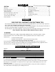
TABLE OF COriTEm______________ SECTION PAGE Warranty............................................................. 2 Product Specifications.............................................. 2 Power Tool Safety .............................................. 3 Table Saw Safety...................................................... 4 Electrical Requirements and Safety.......................... 5 Accessories and Attachments................................... 6 Tools Needed for Assembly..............................
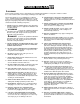
POWER TOOL SAP A WARNING Before using your table saw, it is critical that you read and understand these safety rules. Failure to follow these rules could result in serious Injury or damage to the table saw. Good safety practices are a combination of common sense, staying alert and understanding how to use your power tool. To avoid mistakes that could cause serious injury, do not plug in your power too! until you have read and understood the following safety rules; 16. REMOVE ADJUSTING KEYS AND WRENCHES.
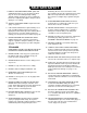
1ABLE SAW SAFETY 1. ALWAYS USE SAW BLADE GUARD, splitter and anti-kickback pawls for every operation for which they can be used, including through-sawing. Through-sawing operations are those in which the blade cuts completely through the workpiece when ripping or cross-cutting. 2. ALWAYS HOLD WORK FIRMLY against the miter gauge or rip fence. 3. USE A PUSH STICK when required. Always use a push stick when ripping narrow stock.
ELECTRICAL REQUIREMENTS AND SAP GROUNDING INSTRUCTIONS IN THE EVENT OF A MALFUNCTION OR BREAKDOWN, grounding provides a path of least resistance for electric currents and reduces the risk of electric shock. This tool is equipped with an electrical cord that has an equipment-grounding conductor and a grounding plug. The plug must be plugged into a matching receptacle that is properly installed and grounded in accordance with all local codes and ordinances. DO NOT MODIFY THE PLUG PROVIDED.
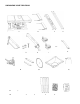
ACCESSORIES AND ATTACHMENTS RECOMMENDED ACCESSORIES A WARNING Visit your Sears Hardware Department or see the Sears Power and Hand Too! Catalog to purchase recommended accessories for this power tool. A WARNING To avoid the risk of personal injury, do not modify this power tool or use accessories not recommended by Sears. CARTON CONTENT Separate ai parts from packing materials.
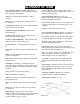
UNPACKING YOUR TABLE SAW 00 K o M 0\0 R Q 00 T U V w
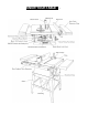
KNOW YOUR TABLE Table Insert 1
GLOSSARY OF TERM ANTI-KICKBACK PAWLS - Prevents the work piece from being kicked upward or back toward the front of the table saw by the spinning blade. ON/OFF SWITCH Contains a built-in safety switch key. To lock the switch in the OFF position, remove the switch key from the switch. ARBOR - The shaft on which the blade or dado is mounted. OVERLOAD RESET SWITCH - Resets the thermocouple and provides a way to restart the saw motor if it overloads or overheats.
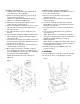
ASSEMBLE STAND (FIG. A) 1. Unpack ai parts and group by type and size. Refer to the parts list for correct quantities. 2. Attach one long upper support (S) to top of leg (V) using one bolt (1) and nut (2). NOTE: Do not tighten bolts until stand is properly aligned (see step #9 before tightening). 3. Attach other end of long upper support to top of another leg using one bolt and nut. 4. Attach one long bottom support (U) to center of each leg using bolt (1) and nut (2).
MOUNT SAW ON WORK SURFACE (FIG. C) 1. If the leg set will not be used, the saw must be properly secured to a sturdy workbench using the four mounting holes at the base of the saw. 2. The surface of the table where the saw is to be mounted must have a hole large enough to facilitate sawdust fall-through and removal. 3. Square the saw on the mounting surface and mark the location of the four 3/8 in. mounting holes (1). 4. Drill 3/8 in. hole into the mounting surface. 5. Mark an 11 in.
RIP FENCE (Fig. G) 1. Lift upward on the rip fence handle (1) so the rear holding clamp (2) is fully extended. 2. Place the rip fence on the saw table, lowering the front of the fence onto the table first. 3. Push down on the fence handle (1) to lock. 4. Remove the arbor nut (5) and outer flange (6) (Fig. I). 5. Install the saw blade onto the arbor with the BLADE TEETH POINTING TOWARD THE FRONT OF THE SAW. 6. Install the flange (6) against the biade and thread the arbor nut (5) as far as possible by hand.
A DANGER BLADE GUARD ASSEMBLY {FIG. K, L, M) 1. Set the blade to maximum height and the tilt to zero degrees on the bevel scale with the hand wheels. Lock the blade bevel lock knob. 2. Place the spring washer (2), flat washer (3), external tooth lock washer (4) onto the blade guard mounting bolt {1) (Fig. K). 3. Insert bolt and washer assembly through splitter bracket (5). Improper splitter alignment can cause “kickback” and serious injury. Fig. m 8 10 INSTALLING TABLE SIDE EXTENSIONS (FIG. N) 1.
INSTALLING THE TABLE SIDE EXTENSIONS- cont’d (FIG. O) 6. Snap one short location seat (1) over the end of the rear table extension tube (2). Make sure the locating pin (3) in the location seat fits into the matching hole in the extension tube (Fig. O). 7. Install the left hand table extension the same manner. ADJUSTING REAR TABLE EXTENSION 1. Rear table extension should be positioned as close as possible to the rear of the table when ripping short work pieces. 2.
RIP FENCE INDICATOR ADJUSTMENT {FIG. Q) 1. The rip fence indicator (6) points to the measurement scale. The scale shows the distance from the side of the fence to nearest side of the blade. 2. Measure the actual distance with a rule. If there is a difference between the measurement and the indicator, adjust the indicator (6). 3. Loosen the screw (7) and slide the indicator to the correct measurement on the scale. Tighten the screw and remeasure with the rule. Fig.
BLADE PARALLEL TO THE MITER GAUGE GROOVE (FIG. U, V) Additional blade adjustments (Fig. V) NOTE: The adjusting nuts are 8mm. The adjusting mechanism is located above the blade height adjusting hand wheel under the tabletop. If the front and rear measurements are not the same. A WARNING This adjustment was made at the factory, but it should be rechecked and adjusted if necessary. If the blade is partial to right side: 1.
OPERATION OVERLOAD PROTECTION (FIG. X) This saw has an overload relay button (3) that resets the motor after it shuts off due to overloading or low voltage. If the motor stops during operation, turn the ON / OFF switch to the OFF position and unplug the saw. Wait about five minutes for the motor to cool. Plug in the saw, push in the reset button (3) and turn the switch to the ON position. BASIC SAW OPERATIONS RAISE THE BLADE (FIG.
CUTTING OPERATIONS There are two basic types of cuts: ripping and crosscutting. Ripping is cutting along the length and the grain of the workpiece. Crosscutting is cutting either across the width or across the grain of the workpiece. Neither ripping nor crosscutting may be done safely freehand. Ripping requires the use of the rip fence, and crosscutting requires the miter gauge. Never use the two cut the same time.
BEVEL RIPPING This cut is the same as ripping except the blade bevel angle is set to an angle other than “0”. USING WOOD FACING ON THE MITER GAUGE (Fig. DD) Slots are provided in the miter gauge for attaching an auxiliary facing (1) to make it easier to cut very long or short pieces. Select a suitable piece of smooth wood, drill two holes through it and attach it the miter gauge face with screws. Make sure the facing does not interfere with the proper operation of the sawblade guard.
COMPOUND MITER CROSSCUTTING (FIG. FF) 0°~45° BLADE BE¥EL & 0°~45° MITER ANGLE This sawing operation is combining a miter angle with a bevel angle. USING WOOD FACING ON THE RIP FENCE (FIG. HH) When performing some special cutting operations, add a wood facing (1) to either side of the rip fence (2). A WARNING 1. Use a smooth straight 3/4 in. thick wood board (1) that is as long as the rip fence. 2. Attach the wood facing to the fence with wood screw (3) through the holes in the fence.
Attach auxiliary fence to rip fence with two “C” clamps. (Fig. JJ) A WARNING For your own safety, always replace the blade, blade guard assembly, and blade insert when you are finished with the dado operation. You must also realign the blade guard assembly. Fig. JJ Fig. KK DADO CUTS (FIG. KK) A WARNING a. Only Stackable dado blades can be used on this saw, b. DO NOT use Adjustable or Wobble type dadoes. c. Maximum dado cut width is V 2 in. 1.
MAIMTENANC Fig. LL GENERAL MAINTENANCE A WARNING For your own safety, turn the switch OFF and remove the switch key. Remove the plug from the power source outlet before maintaining or lubricating your saw. 1. Clean out all sawdust that has accumulated inside the saw cabinet and the motor. 2. Polish the saw table with an automotive wax to keep it clean and to make it easier to slide the work piece. 3. Clean cutting blades with pitch and gum remover. 4.
JJROUBLESHOOTING QUID A WARNING To avoid injury from an accidental start, turn the switch “OFF” and always remove the plug from the power source before making any adjustments. • Consult your local Sears Service Center if for any reason the motor wii not run. SYMPTOM Saw wii! not start. Does not make accurate 45° and 90° rip cuts. Material pinched blade when ripping. Material binds on splitter. Saw makes unsatisfactory cuts. Material kicked back from blade. POSSIBLE CAUSES CORRECTIVE ACTION 1.
PARTS LIS 10 in. TABLE SAW MODEL NO. 137.248840 A WARNING When servicing use only CRAFTSMAN replacement parts. Use of any other parts many create a HAZARD or cause product damage. Any attempt to repair or replace electrical parts on this Table Saw may create a HAZARD unless repair is done by a qualified service technician. Repair service is available at your nearest Sears Service Center. PARTS LIST FOR SAW SCHEMATIC l.D. NO Description Description Size oavH CLAM P-CORD Size 1 OKDR CR.RE. PAN HD.
10 in. TABLE SAW MODEL N0.137.
10 in. TABLE SAW MODEL N0.137.248840 PARTS LIST AND SCHEMATIC FOR STAND Description FOOT PAD FENCE STORAGE CLIP BRACKET UPPER SUPPORT UPPER SUPPORT UPPER SUPPORT BOTTOM SUPPORT BRACKET BOTTOM SUPPORT BRACKET FLAT WASHER FLAT WASHER HEX, HD, BOLT HEX, HD, BOLT OR, RE, ROUND WASHER HD. SCREW HEX, NUT SERRATED TOOTHED HEXAGON FLANGE NUT SERRATED TOOTHED HEXAGON FLANGE NUT CAP HD, SQ.NECK BOLT i.D. NO 09D6 0A4T OEAA OEAN OEAP OEAY 0EB8 OEBG 0J4F 0J4J OJPP OJPX 0K7K OKMU OKRQ OKRR OZIG ' :i3.
10 in. TABLE SAW MODEL NO. 137.248840 PARTS LIST AND SCHEMATIC FOR MOTOR I.D. NO Description Size 0HV8 BALL BEARING Ó201ZLU OHVU BALL BEARING 6200ZZ 0HX9 NEEDLE BEARING OJAL EXT.TOOTH LOCK WASHER 0JX3 0K3A HEX, SOC, SETSCREW 0K5V OKCP CR.-RE. COUND.HD.SCREW OKTH 0QE9 STRAIN RELIEF M5‘0.8-8 MS-O.SOO CR.RE. PAN HD. SCREW & WASHER CR.RE.
шшт
I fi IJ Your Home For repair - in your home - of all major brand appliances, lawn and garden equipment, or heating and cooling systems, no matter who made it, no matter who sold it! For the replacement parts, accessories and Operator’s Manuals that you need to do-it-yourself. For Sears professional installation of home appliances and items like garage door openers and water heaters. 1-800-4-MY-HOME® (1 -800-469-4663) Call anytime, day or night (U.S.A. and Canada) www.sears.com sears.