Operator’s Manual 10 in. TABLE SAW WITH STAND Model No. 137.248850 CAUTION: Before using this Table Saw, read this manual and follow all its Safety Rules and Operating Instructions Customer Help Line For Technical Support 1»800-»843-1682 Sears, Roebuck and Co., Hoffman Estates, IL 60179 USA Visit our Craftsman website: www.sears.com/craftsman Part No.
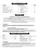
TABLE OF CONTENTS SECTION PAGE SECTION Warranty........................................... Product Specifications..................... Power Tool Safety........................... Table Saw Safety............................. 2 Know Your Table Saw................. 2 Glossary of Terms.............. 3 Assembly and Adjustments. 4 Operation................... Electrical Requirements and Safety.. Accessories and Attachments......... Tools Needed For Assembly........... Carton Contents........................
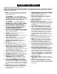
POWER TOOL SAFETY GENERAL SAFETY INSTRUCTIONS Read and understand all the instructions below before using the power tool. These safety instructions are not meant to cover every possible condition that could occur. As with any power tool, common sense, vigilance and due care must be used. 1. READ and become familiar with the entire Operator’ s Manual. LEARN the tool’s application, limitations and possible hazards. A WARNING Look for this symbol that identifies important safety precautions.
TABLE SAW SAFETY 1. ALWAYS USE SAW BLADE GUARD, splitter and anti-kickback pawls for every through-sawing operation. Through-sawing operations are those in which the blade cuts completely through the workpiece when ripping or crosscutting. Always be sure blade guard is tightened securely. 2. ALWAYS HOLD WORK FIRMLY against the miter gauge or rip fence. 3. ALWAYS USE a push stick, especially when ripping narrow stock.
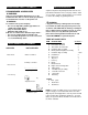
ELEGTRJCAL REQUiREMENTS AND SAF GROUNDING INSTRUCTIONS IN THE EVENT OF A MALFUNCTION OR BREAKDOWN, grounding provides a path of least resistance for electric currents and reduces the risk of electric shock. This tool is equipped with an electrical cord that has an equipment-grounding conductor and a grounding plug. The plug must be plugged into a matching receptacle that is properly installed and grounded in accordance with all local codes and ordinances. DO NOT MODIFY THE PLUG PROVIDED.
ACCESSORIES AND ATTACHMENTS CARTON CONTENTS RECOMMENDED ACCESSORIES A WARNING Visit your Sears Hardware Department or see the Craftsman Power and Hand Tools Catalog to purchase recommended accessories for this power tool. A WARNING A WARNING To avoid the risk of personal injury: • Do not use adjustable (wobble) type dadoes or carbide tipped dado blades. • Only use stackable dadoes. • Maximum dado width is 1/2”. ® Do not use a dado with a diameter larger than 6”.
UNPACKING YOUR TABLE SAW ®®® ® ® ® ® D K f Iff® <9^1 r® “a ® =8 «I aaaa»1 O R M
■ leiliiiliiiiieil
C3LOSSARY OF TERMS ANTI-KICKBACK PAWLS - Prevents the workpiece from being kicked upward or back toward the front of the table saw by the spinning blade. OVERLOAD RESET SWITCH - Resets the thermocouple and provides a way to restart the saw motor if it overloads or overheats. ARBOR - The shaft on which the blade or dado is mounted. PUSH STICK - Used to push workpieces when performing ripping operations. BEVEL CUT - An angle cut made through the face of the workpiece.
ASSEMBLY AND ADJUSTMENTS ASSEMBLING STAND (FIG. A) 1 Unpack all parts and group by type and size. Refer to the parts list for correct quantities. 2. Attach the stand door (3) to the front of the stand base (5) using three screws M5*12-12 (4). 3. Attach the floor plate {1) to the stand (5) using ten screws M5*12-12 (2). See PARTS LIST AND SCHEMATIC FOR STAND SECTION. NOTE: A shelf (not included ) can be added to the stand base (see next section prior to installing the floor plate (1)). 4. Tighten hardware.
MOUNT SAW ON WORK SURFACE 1. if the stand will not be used, the saw must be properly secured to a sturdy workbench using the four mounting holes at the base of the saw. 2. Square the saw on the mounting surface and mark the location of the four 3/8 in. mounting holes. 3. Drill the four 3/8 in. holes into the mounting surface. 4. Place the saw on the work surface, and align the mounting holes of the saw with those drilled through the surface. 5. Fasten the saw to the work surface.
2. Raise the blade arbor (4-Fig. F) to the maximum 3. 4. 5. 6. A WARNING height by turning the blade raising handwheel counterclockwise. Place the open-end wrench (8) jaws on the fiats of the saw arbor to keep the arbor from turning (Fig. G) and place the box-end wrench (9) on the arbor nut (5), and turn counterclockwise. Remove the arbor nut (5) and outer flange (6-Fig. F). install the saw blade onto the arbor with the BLADE TEETH POINTING TOWARD THE FRONT OF THE SAW.
7. When the splitter is properly aligned with the saw blade, tighten the bolt securely. NOTE: The splitter bracket must always be correctly aligned so the cut workpiece will pass on either side without binding or twisting. INSTALLING TABLE SIDE EXTENSIONS (FIG. L, L-1) 1. Identify the right hand table extension. NOTE: For illustration purposes the view in Fig. L looks “through” the saw table to the under side of the table.
5. If fence is loose when the handle is In the locked (downward) position, do the following; • Move the handle (2) upward and turn the adjusting nut (5) clockwise until the rear clamp is snug. • Over-tightening the adjusting screw will cause the fence to come out of alignment. INSTALLING REAR TABLE EXTENSION (FIG. M) 1. Place the rear table extension onto the two rear table extension tubes (1). 2. Snap two long location seats (2) over the two rear table extension tubes (1).
90“ (0“) Stop 1. Disconnect the saw from the power source. 2. Turn the blade elevation handwheel and raise the blade to the maximum elevation. 3. Loosen the blade bevel lock knob (1) and move the blade to the maximum vertical position, then tighten the lock knob (1). 4. Place a combination square on the table and against the blade (2) to determine if the blade is 90° (0°) to the table. (Fig. P) 5.
Fig.S 7. Rotate the blade bringing the marked tooth to the rear and about I/2 in. above the blade. 8. Carefully slide the combination square to the rear until the ruler touches the marked tooth. 9. If the ruler touches the marked tooth at the front and rear position, no adjustment is needed at this time. If not or the base of the rule is no longer parallel with the edge of the miter gauge groove, perform adjustment procedure described in next section. Fig. R BLADE TILTING INDICATOR (FIG. T) 1.
OVERLOAD PROTECTION (FIG. V) This saw has an overload relay button (3) that resets the motor after it shuts off due to overloading or low voltage. If the motor stops during operation, turn the ON / OFF switch to the OFF position and unplug the saw. Wait about five minutes for the motor to cool. Plug in the saw, push in the reset button (3) and turn the switch to the ON position. BASIC SAW OPERATIONS RAISE THE BLADE (FIG.
USING THE DUST CHUTE (FIG. Y) the fence and must not be warped, twisted, or bowed, • Do not allow familiarity or frequent use of your table saw to cause careless mistakes. Remember that even a careless fraction of a second is enough to cause a severe injury. A WARNING To prevent fire hazard, clean and remove sawdust from under the saw frequently. To prevent sawdust buildup inside the saw housing, attach a vacuum hose (1) to the dust chute (2) at the rear of the table saw.
A WARNING • Never attempt to pull the workpiece backwards during a cutting operation. This will cause kickback and serious injury to the user can occur. Never attempt to pull the workpiece backwards during a cutting operation. This will cause kickback and serious injury to the user can occur. When the blade completely stops raise the anti-kickback pawls (4) on each side of the splitter and slide the workpiece out. 1. Remove the rip fence and place the miter gauge a miter gauge groove on the table. 2.
MITERING 0°-45° MITER ANGLE (FIG. FF) This sawing operation is the same as crosscutting except the miter gauge is locked at an angle other than 90°. 1. Adjust the blade (1) to the desired angle, and tighten the blade bevel lock knob. 2. Tighten miter lock handle (2) at 90°. 3. Hold workpiece firmly against the face of the miter gauge throughout the cutting operation. 1. Set the blade (1) to 0° bevel angle and tighten the blade bevel lock knob. 2.
DADO CUTS (FIG. HH) • Only Stackable dado blades can be used on this saw. • DO NOT use Adjustable or Wobble type dadoes. • Maximum dado cut width is 1/2 in. 1. A dado table insert must be purchased separately for this saw to accept a dado blade. Remove saw blade and blade guard for dado cuts ONLY. Reinstall and realign blade guard for all through-sawing operations. Install a dado not exceeding 6 in. in diameter and ’/2 in. in width 2.
MAINTENANCE fyiAINTAINING YOUR TABLE SAW Fig. FF GENERAL MAINTENANCE A WARNING Before maintaining or lubricating the saw, turn switch off, remove the switch key, and unplug the saw. 1. Clean out all sawdust that has accumulated inside the saw cabinet and the motor. 2. Polish the saw table with an automotive wax to keep it clean and to make it easier to slide the workpiece. 3. Clean cutting blades with pitch and gum remover. 4. Immediately replace a worn, cut, or damaged power cord.
TROUBLESHOOTING GUIDE A WARNING To avoid injury from an accidental start, turn the switch OFF remove the switch key and always remove the plug from the power source before making any adjustments. • If for any reason the motor will not run, contact Sears Service Center at 1-800-4-MY-HOME®. SYMPTOM POSSIBLE CAUSES Saw will not start. 1. 2. 3. 4. Saw not plugged in. Fuse blown or circuit breaker tripped. Cord damaged. Debris in on/off switch Does not make accurate 45° and 90° rip cuts. 1.
10 In. TABLE SAW MODEL NO. 137.248850 A WARNING When servicing use oniy CRAFTSMAN repiacement parts. Use of any other parts many create a HAZARD or cause product damage. Any attempt to repair or repiace electrical parts on this Table Saw may create a HAZARD unless repair is done by a qualified service technician. Repair service is available at your nearest Sears Service Center. PARTS LIST FOR TABLE SAW SCHEMATIC 10 . Description LD. Description Size 08VH eoR D eiAM P Size 1 OKMS H EX.
10 in. TABLE SAW MODEL NO. 137.
10 in. TABLE SAW MODEL NO. 137.248850 PARTS LIST AND SCHEMATIC FOR MOTOR l.D. Descirption Size 0HV8 OHVU 0HX9 OJAL 0JX3 0K3A 0K5V OKCP OKTH OQEC 0QM2 OQQT OQRO ORIQ ORIS ORIY 0R20 28TR 2DY4 2EQS 2FLP BALL BEARING BALL BEARING NEEDLE BEARING EXT.TOOTH LOCK WASHER HEX, SOC. SET SCREW CR.RE. PAN HD. SCREW & WASHER CR.-RE, COUND.HD.SCREW CR.RE.
loin. TABLE SAW PARTS L!ST AND SCHEMATIC FOR STAND MODEL NO. 137.248850 I.D. Description SIZE 0J68 0KS2 0KB3 OKBA OKMS OKMY OKRL OVJX 27CC 2ETN 2ETP 2ETQ 2ETR 2ETS 2ETT 2EU3 2EU4 2EW0 2FS2 2FYJ 2FYK 2FYL 2FYN FLAT WASHER CR. RE. COUNT HD. TAPPING SCREW CR. RE. PAN HD. TAPPING SCREW CR. RE. PAN HD. TAPPING SCREW HEX. NUT HEX. NUT U-TYPE NUT HEX. HD. SCREW AND WASHER CR. RE. PAN HD.
NOTES 29
Your Home For repair -- In your home - of all major brand appliances, lawn and garden equipment, or heating and cooling systems, no matter who made it, no matter who sold It! For the replacement parts, accessories and owner’s manuals that you need to do-it-yourself. For Sears professional installation of home appliances and items like garage door openers and water heaters. 1-800-4-MY-HOME® (1-800-469-4663) Call anytime, day or night (U.S.A. and Canada) www.sears.com www.sears.