OWNER’S MANUAL Model No. 139.18887 139.18897 Sears Best For Residential Use Only Caution: Read and follow all safety rules and operating instructions before first use of this product. Fasten the manual near the garage door after installation. 1/2 HP GARAGE DOOR OPENER ■ ■ ■ ■ ■ ■ ■ ■ Safety Precautions Assembly Installation Adjustment Care and Maintenance Operation Troubleshooting Parts List ® Sears Canada, Inc.
Contents Page A review of safety alert symbols.................................2 You'll need tools..........................................................3 Safety information regarding garage door locks and ropes.........................................................3 Testing your garage door for sticking, binding and balance..................................................3 Illustration of sectional door installation .....................4 Illustration of one-piece door installation ..................
You'll Need Tools During assembly, installation and adjustment of the opener, instructions will call for hand tools shown below. Pencil Carpenter's Level 1 Hack Saw 2 Tape Measure Wire Cutters Claw Hammer Drill 3/16", 5/16", and 5/32" Drill Bits Stepladder Pliers Adjustable End Wrench Screwdriver 1/2" and 7/16" Sockets dW h CAUTION WARNING To avoid damage to the garage door and opener, disable locks before installing and operating the opener.
SECTIONAL Door Installation Before you begin, survey your garage area to see whether any of the conditions below apply to your installation. FINISHED CEILING Support bracket & fastening hardware is required. See page 17. Horizontal and vertical reinforcement is needed for lightweight garage doors (fiberglass, steel, aluminum, door with glass panels, etc.). See page 24 for details.
One-Piece Door without Track ONE-PIECE Door Installation Before you begin, survey your garage area to see whether any of the conditions below apply to your installation. FINISHED CEILING Support bracket & fastening hardware may be required. See page 17.
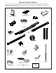
Opener Carton Inventory Your garage door opener is packaged in two cartons which contain all parts illustrated below. If anything is missing, carefully check the packing material. Parts may be "stuck" in the foam. Hardware for assembly and installation is shown on page 7.
Separate all hardware from the packages in the rail carton and the opener carton, as shown below, for the assembly and installation procedures. Assembly Hardware Hex Screw 5/16"-18x7/8" (3) Washered Screw 5/16"-18x1/2" (2) (mounted in opener) Nut 5/16"-18 (5) Trolley Threaded Shaft (1) Carriage Bolt 1/4"-20x1/2" (4) Master Link (2) Lock Washer 5/16" (4) Lock Nut 1/4"-20x7/16" (4) Installation Hardware Lag Screw 5/16"-9x1-5/8" (2) ASE GRE RAIL .
Assembly Section: Pages 8 – 11 To avoid installation difficulties, do not run the garage door opener until instructed to do so. Make sure bolt necks are seated in the square holes and rails are aligned before you tighten lock nuts. (See right and wrong views). Improper assembly can cause jerky trolley operation, noise and/or nuisance door reversals. Assembly Step 1 Assemble the T-rail & Attach the Belt Pulley Bracket • Place the 3 T-rail sections on a flat surface for assembly.
Assembly Step 2 Install the Trolley on the T-rail Trolley • As a temporary stop, insert a screwdriver into the hole in the front end of the T-rail. • Slide the trolley assembly along the rail to the screwdriver stop. If trolley hits against any nuts on the T-rail, the bolts and nuts were attached from the wrong side and must be repositioned. Review Step 1.
Assembly Step 4 WARNING Install the Belt & Set the Belt Tension 1. Drop the notched side of the trolley clip into the retaining slot on top of the trolley (Figure 1). 2. Grasp the clip connector at the end of the belt and slip it through the belt pulley bracket from behind, around the pulley and toward the trolley. 3.
Assembly Step 5 Attach the Belt Cap Retainer To attach the belt cap retainer: • Position the belt cap retainer over the opener sprocket so the two holes in cap align with the two holes in mounting plate. Attach with 8x3/8" hex screws provided. Hex Screws #8x3/8" Belt Cap Retainer Opener Sprocket Mounting Plate Hardware Shown Actual Size Hex Screw #8x3/8" You have now finished assembling your garage door opener.
Installation Section: Pages 12 – 27 Installation Step 1 WARNING Determine Header Bracket Location If the header bracket is not rigidly fastened to a structural support on the header wall or ceiling, the safety reverse system may not work properly (see page 30). The door might not reverse when required, and could cause serious injury or death. The garage door springs, cables, pulleys, brackets and their hardware are under extreme tension. Do not attempt to loosen, move or adjust them yourself.
ONE-PIECE Door Without Track Read the Safety instructions on page 12. They also apply to doors without tracks. Unfinished Ceiling Header Wall Vertical Centerline • Close the door and mark the inside vertical centerline of your garage door. Extend the line onto the header wall above door. If headroom clearance is minimal, you can install the header bracket on the ceiling. See page 14.
You can attach the header bracket either to the wall above the garage door, or to the ceiling. Follow the instructions which will work best for your particular requirements. Installation Step 2 Install the Header Bracket Fasten the Header Bracket to the Wall • Center the bracket on the vertical guideline with the bottom edge of the bracket on the horizontal line as shown (with the arrow pointing toward the ceiling).
Installation Step 3 Attach the T-rail to the Header Bracket • Position the opener on the garage floor below the header bracket. Use packing material as a protective base. If the door spring is in the way you'll need help. Have someone hold the opener securely on a temporary support to allow the T-rail to clear the spring. • Position the belt pulley bracket against the header bracket. • Align the bracket holes and join with a clevis pin as shown. • Insert a ring fastener to secure.
Installation Step 4 CAUTION Position the Opener To prevent damage to steel, aluminum, fiberglass or glass panel doors, do not rest the opener on the door without using a 2x4. Follow instructions which apply to your door type as illustrated. SECTIONAL Door & ONE-PIECE Door with Track A 2x4 laid flat is convenient for setting an ideal door-to-T-rail distance. • Raise the opener onto a stepladder. You will need help at this point if the ladder is not tall enough.
Installation Step 5 WARNING Hang the Opener The opener could fall and injure someone if it is not properly secured. Fasten the opener securely to structural supports of the garage. Two representative installations are shown. Yours may be different. Hanging brackets should be angled, Figure 1, to provide rigid support. On finished ceilings, Figure 2, attach a sturdy metal bracket to structural supports before installing the opener. The bracket and fastening hardware are not supplied.
Installation Step 6 WARNING Install the Premium Control Console Do not connect to live electrical wiring. Connect only to 24 Volt low voltage wires. Connection to live wires or higher voltage may cause serious injury from shock, burn or electrocution. Children operating or playing with a garage door opener can injure themselves or others. The garage door could close and cause serious injury or death.
6. Attach the User Safety Instruction label to the wall near the door control, and the Maintenance Instruction label in a prominent location on the inside of the garage door. Do NOT connect the power and operate the opener at this time. The trolley will travel to the full open position but will not return to the close position until the sensor beam is connected and properly aligned. See Safety Reversing Sensor instructions beginning on page 21. Page 32 explains how to use the door control.
Installation Step 9 WARNING Electrical Requirements To prevent electrocution or fire , installation and wiring must be in compliance with local electrical and building codes. Do NOT use an extension cord, 2-wire adapter, or change the plug in any way to make it fit your outlet. To reduce the risk of electric shock, your garage door opener has a grounding type plug with a third grounding pin. This plug will only fit into a grounding type outlet.
The Safety Reversing System Information you'll need before you begin the installation of the safety reversing sensor. The safety reversing sensor must be connected and aligned correctly before the garage door opener will move in the down direction. This is a required safety device and cannot be disabled. WARNING Without a properly working safety reversing sensor, persons (particularly children) could be injured or killed by a closing garage door. Read and follow all instructions.
Installation Step 10 Install the Safety Reversing Sensor Figure 2 Figures 2 and 3 show assembly of brackets and "C" wrap based on the recommended installation of the sensors as shown on page 21. However, Figures 4 and 5 are variations which may fit your installation requirements better. Make sure the wraps and brackets are aligned so the sensors will face each other across the garage door. • Fasten the "C" wraps to the mounting brackets having square holes, using the hardware shown in Figure 2.
Figure 6 • Center each sensor unit in a "C" wrap with lenses pointing toward each other across the door (see Figure 6). • Secure sensors with the hardware shown. Finger tighten the wing nut on the receiving eye to allow for final adjustment. Securely tighten the sending eye wing nut. • Run the wires from both sensors to the opener. Use insulated staples to secure wire to wall and ceiling. • Strip 1/4" of insulation from each set of wires.
Installation Step 11 CAUTION Fasten Door Bracket To prevent damage to steel, aluminum, fiberglass or glass panel doors, always reinforce the inside of the door both vertically and horizontally with an angle iron. Follow instructions which apply to your door type as illustrated below or on page 25. A horizontal brace should be long enough to be secured to 2 vertical supports. A vertical brace should cover the height of the top panel.
All ONE-PIECE Door Installation Procedure Please read and comply with the warnings and reinforcement instructions on page 24. They apply to one-piece doors also. Header Wall 2x4 Support Finished Ceiling Horizontal and vertical reinforcement is needed for lightweight garage doors (fiberglass, aluminum, steel, door with glass panel, etc.).
Installation Step 12 Connect Door Arm to Trolley Follow instructions which apply to your door type as illustrated. SECTIONAL Doors Only Make sure garage door is fully closed. Pull the emergency release handle to disconnect the outer trolley from the inner trolley. Slide the outer trolley back (away from the door) about 2" as shown in Figures 1, 2 and 3. Figure 1: • Fasten straight door arm section to outer trolley with the 5/16"x1" clevis pin. Secure the connection with a ring fastener.
All ONE-PIECE Doors Can/DoorArmToTrolley 1 c Assemble the Door Arm: • Fasten the straight and curved door arm sections together to the longest possible length, with a 2 or 3 hole overlap. • With the door closed, connect the straight door arm section to the door bracket with the 5/16"x1-1/4" clevis pin. • Secure with a ring fastener.
Adjustment Section: Pages 28 – 30 Adjustment Step 1 WARNING Adjust the UP and DOWN Limits Do not make any limit adjustments until the safety reversing sensors are completely installed. Improper adjustment of the travel limits will interfere with the proper operation of the safety reverse system. The door might not reverse properly when required and could seriously injure or kill someone under it. Test the safety reverse system following all adjustments to the travel limits. See page 30.
Adjustment Step 2 WARNING Adjust the Force Too much force on the door will interfere with the proper operation of the safety reverse system. The door might not reverse properly when required and could seriously injure or kill someone under it. Do not increase the force beyond the minimum amount required to close the door. Do not use the force adjustments to compensate for a binding or sticking garage door. Test the safety reverse system following all adjustments to force levels. See page 30.
Adjustment Step 3 WARNING Test The Safety Reversing Sensor Without a properly working safety reversing sensor, persons (particularly children) could be seriously injured or killed if trapped by a closing garage door. Repeat this test once a month. • Press the remote control push button to open the door. • Place the opener carton in the path of the door. • Press the remote control push button to close the door. The door will not move more than an inch, and the opener lights will flash.
IMPORTANT SAFETY INSTRUCTIONS WARNING WARNING To reduce the risk of severe injury or death to persons: 1. READ AND FOLLOW ALL INSTRUCTIONS. 2. Do not permit children either to operate or to play with the opener. Keep remote control in a location inaccessible to children. 3. Operate opener only when the door is in full view and free from any obstruction. Keep the door in sight until it is completely closed. NO ONE SHOULD CROSS THE PATH OF THE MOVING DOOR. 4. Check safety reversal system monthly.
Operation of Your Opener Activate the opener with any of the following: • The Remote Control: Hold push button down until the door starts to move. • The Door Control: Hold push button down until the door starts to move. • The Outdoor Key Switch or Keyless Entry: (See Accessories) When the opener is activated with the safety reversing sensor installed and correctly aligned: 1. If open, the door will close. If closed, it will open. 2. If closing, the door will reverse. 3.
Receiver and Remote Control Programming To comply with FCC/IC rules, adjustment or modifications of this receiver and/or transmitter are prohibited, except for changing the code setting or replacing the battery. THERE ARE NO OTHER USER SERVICEABLE PARTS. WARNING Children operating or playing with a garage door opener can injure themselves or others. The garage door could close and cause serious injury or death. Do not allow children to operate the door push button(s) or remote control(s).
Having a Problem? Situation Probable Cause and Solution The opener doesn't operate from either the Door Control or the remote control: 1. Does the opener have electric power? Plug a lamp into the outlet. If it doesn't light, check the fuse box or the circuit breaker. (Some outlets are controlled by a door switch.) 2. Have you disabled all door locks? Review installation instruction warnings on Page 11. 3. Is there a build-up of ice or snow under the door? The door may be frozen to the ground.
Having a Problem? (continued) Situation Probable Cause & Solution The door opens but won't close: 1. If the opener lights blink, check the safety reversing sensor. See page 23. 2. If the opener lights do not blink and it is a new installation, check the down force. See Adjustment Step 2, page 29. For an existing installation, see below. Repeat the safety reverse test after the adjustment is complete. The door reverses for no apparent reason and opener lights don't blink: 1.
Repair Parts Rail Assembly Parts 3 4 2 1 5 9 6 RAGE TO GA DOOR KEY NO. 4 8 E AS GRE RAILO. 83A4 N 7 1 2 3 4 5 6 7 8 9 PART NO.
Repair Parts Opener Assembly Parts 1 2 4 9 7 3 5 6 8 20 8 10 11 12 3 18 19 9 15 13 16 5 17 14 Brown Wire (Down) Contact LIMIT SWITCH ASSY. DN UP Drive Gear Center Limit Contact KEY PART NO. NO.
Accessories Sears offers many useful accessories for your garage door opener. They are illustrated below with Sears model numbers and descriptions. 18752 Outside Trolley Release: Required for a garage with NO access door. 18792 SECURITY✚ Compact 3-Function Remote Control: With loop for attaching key ring. 18756 Outdoor Key Switch: Opens the garage door automatically from outside when remote control is not handy. 18791 SECURITY✚ 3-Function Remote Control: Includes visor clip.
Index Access Door/Outside Key Release Accessory ...............................................................................................4, 5 Belt Tension .................................................................................................................................................4, 5, 11 Electrical Safety Warnings........................................................................................................................
Sears Best OWNER’S MANUAL Model No. 139.18887 139.18897 ® GARAGE DOOR OPENER SERVICE AND REPAIR PARTS CALL 1-800-665-4455* Keep this number handy should you require a service call or need to order repair parts. If ordering parts make sure you have the name, make and model no. of the merchandise and the name and number of the part you wish to order. To purchase a Sears Maintenance Agreeement – ask any salesperson or call Sears Service today.