00000 OD 139 1 1 39°53606 1 39.5361 0 - 1/3HP - 1/2 HP = 1/2 HP ° 1/3 HP Owners Manual CAUTION READ INSTRUCTIONS FOR SAFE OPERATION AND RULES CAREFULLY CONTENTS PAGE Features of Your Opener ............. Specifications .......................... Accessories ............................... Carton Check List ...................... You'll Need Tools .................... Safety Rules .............................. Operation of Your Opener ............ Maintenance Schedule ...............
FEATURES OF YOUR OPENER 1. Motor: Permanently reset, lubricated with automatic 5. 2. Opener Light: Turns on and off automatically. Provides 4-1/2 minute illumination for your safety and convenience, 6. 3. Safety System: Independent up and down force adjustment. Door reverses automatically when obstructed in DOWN direction Door STOPS when obstructed in UP direction 4. 7. 8.
CARTON CHECK LIST SEARS has packaged yourGarage Door Opener illustrated below and on Page 22. Sprocket Cover SEPARATE Rail Grease ALL HARDWARE ASSEMBLY in two cartons Light FOR ASSEMBLY which contain all the parts and hardware Transmitters {2) Model 13953413 (1 ONLY) Touch Code Lock (1) Model 139 53610 ONLY Lens (1) AND INSTALLATION HARDWARE PROCEDURES INSTALLATION AS SHOWN BELOW.
Start By Reading These Impo ant Safety Rules THIS SAFETY ALERT SYMBOL MEANS CAUTION -- PERSONAL SAFETY OR PROPERTY DAMAGE INSTRUCTION. READ THESE INSTRUCTIONS CAREFULLY° THIS GARAGE DOOR OPENER IS DESIGNED AND TESTED TO OFFER REASONABLY SAFE SERVICE PROVIDED IT IS INSTALLED AND OPERATED IN STRICT ACCORDANCE WITH TH E FOLLOWING SAFETY INSTRUCTIONS. FAILURE TO COMPLYWITH THE FOLLOWING PERSONAL INJURY OR PROPERTY DAMAGE, CAUTION: IF YOUR GARAGE HAS NO SERVICE KEYLOCK (PAGE 2).
Operation of Your Opener CAUTION e BEFORE YOU PROCEED, PLEASE READ THE SAFETY RULES ON PAGE 4 AND OPERATING INSTRUCTIONS ON THIS PAGE CAREFULLY. • DO NOT PERMIT CHILDREN TO PLAY IN DOOR AREA. • OPERATEONLYWHENTHEOPENERISPROPERLYADJUSTED AND DOOR IS WSIBLE AND UNOBSTRUCTED. e TO AVOID DIFFICULTY DURING INSTALLATION, DO NOT RUN OPENER UNTIL INSTRUCTED TO DO SO.
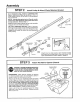
Assembly TO AVOID INSTALLATION INSTRUCTED TO DO SO. ST _: P DIFFICULTIES, "1 DO NOT Assemble RUN THE GARAGE Tee Rail & Attach DOOR Cable OPENER UNTIL YOU ARE Pulley Bracket TEE RAIL BACK (TO CHASSIS) CAUTION: Do not tighten the lock nuts until bolt necks are seated in square holes. Tee Rail (End Section) t/4' Lock Nut Carriage Bolt /2" Tee Rail Brace _ PROCEDURE: Place the 3 Tee rail sections on a flat surface for assembly. THIS IS IMPORTANT. The end sections are identical.
Assernbiy STE P 2 Install Trolley & Attach Chain Retainer Bracket As a temporary stop, insert a screwdriver into hole in front end of Tee rail as shown. Slide the inner trolley onto the Tee rail until it is firmly against the screwdriver NOTE: If trolley hits against nut on Tee rail, center section was attached from wrong side and must be repositioned. Review Step 1.
Assembly STE P 4 I.stallChain andCable DO NOT REMOVE CHAIN AND CABLE FROM CARTON Detach cable from side of carton and fasten to trolley with a master link from coin envelope I=! install Chain andCable inThisDirection Opener Chassis Sprocket / MASTER LINK PROCEDURE: Push pins of master link bar through loop of cable and hole in flat end of trolley shaft (A) Push cap over pins and onto notches.
Assembly STE P 5 Loosen Inner Nut Tighten the Chain and Cable CAUTION: Keep are turned. Tighten Outer Nut PROCEDURE: shown (Loosen the chain from twisting as nuts Thread the outer nut toward trolley as inner nut first, if"necessary) Tension is correct when the chain is approximately 1/2" above base of Tee rail midway between cable pulley bracket and chassis. Trolley To maintain proper tension, turn inner nut toward chain retainer bracket until tight Chain Sprocket noise can loose or too tight.
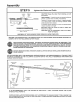
installation STE P 1 Installation procedures your door as illustrated Position vary according below., & Install Header Bracket to garage door types.
installation STE P 2 Clevis Pin 5/16 'x2-3/4 @/_ A.ach Tee Rail Cotter Ring OrpinI Fastener to Header Bracket PROCEDURE: Position opener chassis on garage floor below header bracket. Use packing material base to protect cover NOTE: To enable Tee rail to clear sectional door springs, it may be necessary to lift the chassis onto a temporary support.
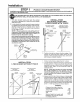
installation STEP 4 THE OPENER CHASSIS MUST BE Three representative installations (Fig. 1 ) or crossed (Fig. 2) to provide (not supplied) to ceiling joists before Hang Opener Chassis SECURELY FASTENED TO A STRUCTURAL SUPPORTOF GARAGE. are shown. You rs may be different. Hanging brackets should be angled rigid support On finished ceilings (Fig. 3).
LOCATE WALL PUSH BUTTON (OR ANY ADDITIONAL PUSH BUTTONS) WHERE GARAGE DOOR IS VISIBLE, AWAY FROM DOOR AND DOOR HARDWARE AND OUT OF THE REACH OF CHILDREN. SERIOUS PERSONAL INJURY FROM A MOVING GARAGE DOOR MAY RESULT FROM MISUSE OF THE OPENER° DO NOT ALLOW CHILDREN TO OPERATE WALL PUSH BUTTON(S) OR THE TRANSMITTER. FASTEN THE CAUTION LABELON THE WALL NEAR WALL PUSH BUTTON AS A REMINDER OF SAFE OPERATING PROCEDURES.
Installation STE P 7 Install Light and Lens PROCEDURE: Install a light bulb, (75 Watts Maximum) in socket as shown The light will turn on and remain lit for 4-!/2 minutes when power is connected After 4-1/2 minutes it will turn off If light bulb burns out prematurely tion, replace with a "rough service" INSTALLING Guide Len due to vibrabulb.
Installation STE P 9 Follow instructions Install Door Bracket and Plate which apply to your door type as illustrated below TO PREVENT DAMAGE TO LIGHTWEIGHT GARAGE DOORS, ALWAYS REIN FORCETHE OF DOOR--BOTH VERTICALLY AND HORIZONTALLY--WITH 2x4 BOARDS OR ANGLE INSIDE IRON. Horizontal brace should be at least 6 feet long Vertical brace should cover height of top panel The best solution is to check with your garage door manufacturer for a door reinforcement kit for an opener installation.
installation STE P 10 Follow only Connect those instructions SECTIONAL DOOR to your type ONLY Pull the emergency release rope to disengage trolley. Bring arm sections together and insert screw into second of holes Instalf lock washer and nut Tighten screws Proceed to Step 1, Pg. 17. The trolley automatically when opener is operated. as far will set re-engage C B A door FIG. C.
Adjustment STEP 1 AdjustUPandDOWN Limits LIMIT ADJUSTMENT settings regulate the points at which the door will stop when moving up or down NOTE: Door STOPS in UP direction if anything inter- _ o _'_"_ direction if anything interferes with door travel (including binding or unbalanced doors). fereswithdoortraveI. The door REVERSES in DOWN button or transmitter.
Adjustment STEP 3 Test Safety Reverse System TH E SAFETY REVERSE SYSTEM TEST IS IM PORTANT. THE GARAGE DOOR MUSTREVERSE ON CONTACT WITH A ONE INCH OBSTACLE PLACED ON THE FLOOR. FAILURE TO PROPERLY ADJUST OPENER MAY RESULT IN SERIOUS PERSONAL INJURY FROM A CLOSING GARAGE DOOR. REPEAT TEST AT LEAST FOUR TIMES A YEAR AN D ADJUST AS NEEDED.
Radio Controls Your 3-channel transmitter(s) will operate more than one garage door opener, if desired, Also, refer to the catalog packed with your opener for remote light products which can be operated by the additional push buttons on the transmitter(s).
Having a Problem? SITUATION PROBABLE OPENER DOESN'T OPERATE FROM EITHER WALL PUSH SUTTON OR TRANSMITTER 1. Have you disengaged all door locks? Review Step 8, Page 14 2. Does the opener have electric power? Plug a lamp into the outleL If it doesn't light, check fuse box or circuit breaker (Some outlets are controlled by a wall switch). 3. Repeated operation may have tripped the overload protector in the motor. Wait 15 minutes Try again 4.
Having a Problem? (Continued) PROBABLE SITUATION i CAUSE ,i I & SOLUTION i,ii .... iiI DOOR WON'T CLOSE 1 The infrared Reversing Sensor (if you have instaIJed this accessory} may be misaligned or obstructed.
Repair Parts RAI L ASSEMBLY PARTS LIST KEY NO. 1 2 3 4 5 6 7 8 I PART NO. DESCRIPTION 1A995 41 B2617 41 B2771 12A197 2B313 183B93 4182616 41 C2735 Master link kit Outer trolley Inner trolley Chain retainer bracket Tee ratFcenter section Tee raiFend section (each) Cable pulley bracket assy (each) Chain and cable NOT SHOWN 41A2814 Rail assy iflustrated hardware kit (includes on Page 3) hardwar( ',"sTAL-L_,T,0" PA41:sLisi: ........................................................................ i.
Repair Chassis Parts Assembly Parts List 6 21 18 7 3 16 11 15' 14 12 KEY NO. PART NO.
S=FiA! S/ i; Owners Garage Door Manual HOW TO ORDER REPAIR PARTS Now that you have purchased your Sears Garage Door Opener, should you ever need repair parts or service, simply contact any Sears Service Center and most Sears, Roebuck and Co stores Be sure to provide all pertinent facts when you call or visit, Opener Models: 139.53403 139o5341 3 139=53606 139o5361 0 The MODEL NUMBER of your garage door opener is printed on a label located on the front panel of the opener chassis.