Owner's Manual Model No. 139.53661SRT1 139.53671SRT1 139.53672SRT1 139.53673SRT1 139.53674SRT 139.53677SRT1 / For Residential Use Only CRAFTSMRN® GARAGE DOOR OPENER Caution: Read and follow all safety rules and operating instructions before first use of this product. Fasten the manual near the garage door after installation.
Contents Page A review of safety alert symbols ................................. 2 Contents Page Install the light and lens ................................................. 19 You'll need tools.......................................................... 3 Attach emergency release rope and handle ................. 19 Safety informationregarding garage door locks and ropes .................................................................. 3 Safety reversing sensor information............................
You'll Need Tools During assembly, installation and adjustment of the opener, instructions will call for hand tools shown below. Pencil Oooel Lev_ OOO O Hack Saw Ta_e Measure W3re Cutters ClawHammer 3116", 5116" awJ 5/32" Drill Bits _rewdl'iver Step_adder Adjustable End Wrench An unbalanced garage door might not reverse when required and someone under the door could be seriously injured or killed. If your garage door binds, sticks or is out of balance, call for professional garage door service.
Before you begln, survey your garage area to see whether any of the conditions below apply to your installation. FINISHED CEILING SuI_ bracket & fastlming hardware Horizontal and vertical reinforcement iS needed to_'llghtw_ght _ doors (fiberglass. steel, akJminum, door v_th glass panels, etc.). See page 24 for details. Seg page 17.
One-Piece Before you begin, survey your garage ares to see whether any of the conditions below apply to your installation. Door Without Track FINISHED CEILING Support bracket & faslening in chain thns_on is normal when hardware is required. See page t7. garage door is dosed. Header Wa!l Closed Position Cable / Pultey Bracket Bracket O Cable Trolley T-rail DoorSrac_xet Release Door Arm Coot ) betweenfloorand bottom ReversingSensor of doormustnot exceed I/4".
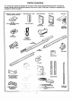
Carton Inventory Your garage door opener is packaged in two cartons which contain all pads illustrated below. If anything is missing, carefully check the packing material. Parts may be "stuck" in the foam. Hardware for assembly and installation is shown on page 7. Models 5366t (1), 53671 (1), 53672 (2). 53673 (2), 53674 (2).
Sel_arate all hardware from the packages shown below, for the assembly and installation Assembly Washered Screw 5/16"-183(1/2"(2) (mounted in opener) Hex Sorew 5/16".18xTir (3) Trolley'i_maded in the rail carton and the opener carton, as Carriage Bolts 114--20xl/2" (4) Master Unk (2) procedures. Hardware Nut 5/16".
Assembly Section: Pages 8- 11 To avoid installation difficulties, do not run the garage the T.rail & Attach the Cable Pulley until Make sure bolt necks are seated In the square _ holes end rails are _ aligned beforeyou _ • Assembly Step I Assemble door opener .omenlo (Sas __ Bracket instructed _k A_P'-"-"-'_I'--_ t• _• I i right and wrong views). '_k to do so. . | / J • '_ iImproper assembly can _ cause ]edo/trolley operation,noise and/or nuisancedoor reversals.
Assembly Hardware Shown Actual Size Step 2 Install the Trolley on the T-rail ©© • Attach the threaded shaft to the trolley with the lock washer and nuts as shown. Lock Washer 5/16" Nut 5/16" - 18 LockWasher 5/16" Outer Nut Tro!ley Threaded Shaft InnerNut 5/16" 5/16"_ Trolley TemporarySlop Screwdriver • As a temporary stop, insert a screwdriver into the hole in the front end of the T-rail. • Slide the trolley assembly along the rail to the screwdriver stop.
u Assembly Step 4 WARNINQi Install the Chain/Cable & Attach the Sprocket Cover i i i i i • i Serious injury can result if fingers become entangled in moving opener sprocket. Attach sprocket cover securely. Never operate opener while your hand is near the opener sprocket. Figure 2 c._.,. Sprockel Keep Chain and Cable Taut When Dispensing • Detach the cable loop from the carton and fasten it to the trolley with a master link from the hardware bag. See master link procedure, Figure 1.
Assembly Step 5 Tighten the Chain & Cable I Lock Outer Nut • Spin the inner nut and lock washer down the threaded shaft, away from the trolley. Washer TO "ilghten Outer Nut --'_"_ • To tighten the chain, turn outer nut in the direction shown. As you turn the nut, keep the chain from twisting. • When the chain is approximately 1/2" above the base of the T-rail at its midpoint, re-tighten the inner nut to secure the adjustment.
Installation Installation Determine Section: Pages 12- WARN Step I Header Bracket Location If the header bracket is not rigidly fastened to a structural support on the header wall or ceiling, the safety reverse system may not work properly (see page 30). The door might not reverse when required, and could cause serious injury or death. The garage door springs, cables, pulleys, brackets and their hardware are under extreme tension. Do not attempt to loosen, move or adjust them yourself.
Read the Safety instructions on page 12. They also apply to doors without tracks. Header Wall 2x4 • Close the door and mark the inside vertical centedine of your garage door. Extend the line onto the header wall above door. If headroom clearance is minimal, you can install the header bracket on the ceiling. See page 14.
i Install the Header Bracket Installation Step 2 You can attach the header bracket either to the wall above the garage door, or to the ceiling. Follow the Instructions which will work best for your particular requirements, I Fasten the Header • Center the bracket on the vertical guideline with the bottom edge of the bracket on the horizontal line as shown (with the arrow pointing toward the ceiling).
ii Attach the T-rail to the Header Installation Step 3 Bracket [ • Position the opener on the garage floor below the header bracket. Use packing material as a protective base. If the door spring is In the way you'll need help. Have someone hold the opener securely on a temporary support to allow the T-rail to clear the spring. Header BW // // // • Position the cable pulley bracket against the header bracket. // • Align the bracket holes and join with a clevis pin as shown.
Installation Position Step 4 the Opener Follow instructions type as Illustrated. which apply to your door i A 2x4 laid flat is convenient for setting an Ideal door-toT-rail distance. T-ra_ • Raise the opener onto a stepladder. 2x4 I You will need help at this point ff the ladder is not tall enough. • Open the door all the way and place a 2x4 laid flat on the top section beneath the T-rail.
I Installation Step 5 Hang the Opener Two representative Installations are shown. Yours may be different. Hanging brackets should be angled, Figure 1, to provide dgid support. On finished ceilings, Figure 2, attach a sturdy metal bracket to structural supports before installing the opener. The bracket and fastening hardware are not provided. See accessory page 38. Figure I _ StructuraJ • Measure the distance from each side of the opener to the structural support.
Installation Step 6 Install the Door Control I Do not connect to live electrical widng. Connect only to 24 Volt low voltage wires. Connection to live wires or higher voltage may cause serious injury from shock, burn or electrocution. Children operating or playing with a garage door opener can injure themselves or others. The garage door could close and cause serious injury or death.
, 6. Attach the User Safety Instruction label to the wall neat the door control, and the Maintenance Instruction label in a prominent location on the inside of the garage door. Do NOT connect the power and operate the openerat this time. The trolley will travel to the full open position but wilt not return to the close position until the sensor beam is connected and properly aligned. See Safety Reversing Sensor instructions beginning on page 21. Page 32 explains how to use the door control.
Installation Electrical Step 9 Requirements To prevent electrocution or fire, installation and wiring must be In compliance with local electrical and building codes. Do NOT use an extension cord, 2-wire adapter, or change the plug In any way to make it fit your outleL To reduce the risk of electric shock, your garage door opener has a grounding type plug with a third grounding pin. This plug will onlyfit into a grounding type outlet.
The Safety Reversing Information you'll need before you begin the installation System of the safety reversing sensor, The safety reversing sensor must be connected and aligned correctly before the garage door opener will move In the down direction. This is a required safety device and cannot be disabled. Installation procedures are the same for sectional and one-piece doors. Read and follow all Instructions.
I Installation Step 10 Install the Safety Reversing Sensor Figure 2 ' Figures 2 and 3 show assembly of brackets and i "C" wrap based on the recommended installation of the sensors as shown on page 21. Mo_ Brac_l W'dhSquareHoles However, Figures 4 and 5 are vadetions which may fit your installation requirements better.
• Center each sensor unit in a "C" wrap with lenses pointing toward each other across the door (see Figure 6). Figure 6 • Secure sensors with the hardware shown. Finger tighten the wing nut on the receiving eye to allow for final adjustment. Securely tighten the sending eye wing nut. 114-20x 1-1/2° FlexBoat • Hun the wires from both sensors to the opener. Use insulated staples to secure wire to wall and ceiling. Trouble Shooting • Strip 1/4" of insulation from each set of wires.
Installation Step 11 Fasten Door Bracket To prevent damage to steel, aluminum, fiberglass or glass panel doors, always reinforce the inside of the door both vertically and horizontally with an angle iron. Follow instructions which apply to your door type as illustrated below or on page 25. A horizontal brace should be long enough to be secured to 2 vertical supports. A vertical brace should cover the height of the top panel. The illustration shows one piece of angle iron as the horizontal brace.
Please read and comply with the warnings and reinforcement instructions on page 24. They apply to one-piece doors also. • Center the bracket on the top of the door, in line with the header bracket as shown. Mark holes Hardware Shown Actual Size • Ddl! 5/16" pilot holes and fasten the door bracket with hardware supplied, © If the door has no exposed framing, drill 3/16" pilot holes and fasten the bracket with 5/16=x1-I/2" lag screws (not provided) to the top of the door.
Installation Connect Step 12 Door Arm to Trolley Follow Instructions which apply to your door type as illustrated below and on page 27. Make sure garage door is fully closed. Pull the emergency release handle to disconnect the outer trolley from the inner trolley. Slide the outer trolley back (away from the door) about 2" as shown in Figures 1, 2 and 3. Figure 1: Figure 2: Fasten straight door arm section to outer trolley with the 5/16"x1" clevis pin. Secure the connection with a ring fastener.
Assemblethe DoorArm: • Fasten the straight and curved door arm sections together to the longest possible length (with a 2 or 3 hole ovedap). PJ_ ooor • With the door closed, connect the straight door arm section to the door bracket with the 5/16"xl -1/4" clevis pin. cle_sF_n _ls'xl.t/4" SctN 5/16"-18X7/8 • Secure with a ring fastener. On one-piece doors, before connectingthe door arm to _ trolleythe travel limits must be adjusted.
Adjustment Adjustment Adjust Section: Pages 28 - 30 Step 1 the UP and DOWN Limits Do not make any limit adjustments until the safety reversing sensors are completely installed. Limit adjustment settings regulate the points at which the door wilt stopwhen moving up or down. The door will stop i6the up direction if anything interferes with door travel. The door will reverse in the down direction if anything interferes with the door travel (including binding or unbalanced doors).
Adjustment Adjust Step 2 WARNING the Force I Too much force on the door will interfere with the proper operation of the safety reverse system. The door might not reverse properly when required and could seriously injure or kill someone under iL Do not increase the force beyond the minimum amount required to close the door. Do not use the force adjustments to compensate for a binding or sticking garage door. Test the safety reverse system following all adjustments to force levels. See page 30.
Adjustment Step 3 Test The Safety Reversing Sensor I • Press the remote control push button to open the door. • Place the opener carton in the path of the door. • Press the remote control push button to close the door. The door will not move more than an inch, and the opener light will flash. Professional serv.lce is required if the opener closes the door when the safety reversing sensor is obstructed.
IMPORTANT ' ':-, SAFETY ;,.i INSTRUCTIONS ! f.. To reduce the risk of severe injury 1. READ AND FOLLOW ALL INSTRUCTIONS. WARNING , , , , , i i or death to persons: 5. If possible, use the emergency release only when the deer is in a closed position. Caution should be taken whenever the disconnect cord is actuated with the door open. Weak or broken springs may cause the door to fall rapidly, causing injury or death to persons. 6. KEEP GARAGE DOORS PROPERLY BALANCED. See page 3.
Operation of Your Opener Activate the opener with any of the following: • The Remote Control: Hold push button down until the door starts to move. • The Door Control: Hold push button down until the door starts to move. Weak or broken springs could allow an open door to fall (either rapidly or unexpectedly), resulting in serious injury, death or property damage. If possible, use the emergency release rope and handle only when the door is fully closed. • The Outdoor Key Switch or Keyless Entry.
Receiver and Remote Control Programming To comply with FCO roles, adjustment or modifications of _s receiver and/or I_ilter are ptohlbited, except for changing the code setling or ,_placing Ihe battery. THERE ARE NO OTHER USER SERVICEABLE PARTS. SECURITY Your garage door opener receiver and remote control have been pre-set at the factory. The door will open when you press the LARGE remote control push button.
Having a Problem? Situation Probable Cause and Solution The opener doesn't operate from either the Door Control or the remote control: 1. Does the opener have electric power?. Plug a lamp into the outlet, ff it doesn't light, check the fuse box or the cimuit breaker. (Some outlets are controlled by a wail switch.) 2. Have you disabled all door locks? Review installation instructionwamings on Page 11. 3. Is there a build-up of ice or snow under the door?.The door may be frozen to the ground.
Having a Problem? (continued) Situation Probable The door opens but won't close: 1. If the opener lights blink, check the safety reversing sensor. See page 23. 2. If the opener lights do not blink and it is a new installation, check the down force. See Adjustmenr Step 2, page 29. For an existing installation, see below. Cause & Solution Repeat the safety reverse test after the adjustment is complete.
Repair Parts Rail Assembly Parts KEY NO. Installation Parts PART NO. DESCRIPTION 1 1A995 Master link kit 2 3 41A3489 1B3117 Complete trolley assembly T-rail - center section 4 5 6 183Bt 10 83A4 41A3473 T-rail - end section (each) Rail grease Chain and cabts 7 41 B2616 Cable pulley bracket assembly NOT SHOWN 41A3534 Rail assembly hardware kit (see page 7), FORREMOTEM00EL 139._I 2 KEY PART NO. NO.
Repair Parts Opener Assembly Parts I ,ok1 ""_ ,'_ -G, 1" "---.-. _i_i_,,-- _ 18 17 116 '"--.. "--...6_ 3 .' .. [ yS'_e'--_];i_'_:_13 " LIMITSWITCH __ "_ G_ Centre" Lim_ (Up) CoaU_ Co_a_ KEY PART NO. NO. 1 2 31D380 41C4220A 3 41A2817 4 5 6 7 8 41 B4245 41A4352 175B88 108D48-2 30B363 30B387 12A373 41A3150 9 10 _ yellow wh KEY PART NO, NO. DESCRIPTION 11 Sprocket cover Gear and sprocket assy.
Accessories Sears offers many useful accessories for your garage door opener. They are illustrated Sears model numbers and descriptions. 139.53681 Emergency Key Release: SECURITY.Ik 3-FuncUon Remote Control: Required for a garage with NO access door. Enables homeowner to open garage door manually from outside by disengaging trolley. Includes visor clip. 139.53680 139.
Index Access Door/Outside Key Release Accessory ............................................................................................... 4, 5 Chain Tension .............................................................................................................................................. 4, 5, 11 Electrical Safety Warnings ........................................................................................................................
For professional installation Call 24 hours a day, 7 days a week 1-800-865-6500 For the repair or replacement parts you need Call 7 am - 7 pm, 7 days a week t -800-366-PART (1-800-366-7278) For in-home major brand repair service Call 24 hours a day, 7 days a week t -8OO-4-REPAIR (1-800473-7247) For the location of a Sears Repair Service Center in your area Call 24 hours a day, 7 days a week 1-8OO-488-1222 For Information on purchasing a Sears Maintenance Agreement about an existing Agreement C