Owner's Manual Model No. 139.53664SRT2 For Residential Use Only CRRFTSMI:iN® GARAGE DOOR OPENER 1/2 HP Caution: Read and follow all • Safety Precautions safety rules and operating instructions before first use of this product, • Installation Fasten the manual near the garage door after installation, Complies withUL325 regulations effective January 1, 1993 f|ll • Assembly • Adjustment • Care and Maintenance • Operation • Troubleshooting • Parts List _ Sears, Roebuck and Co.
Contents Page A review of safety alert symbols ................................. 2 You'll need tools .......................................................... 3 Contents Page Install the lights and lenses ...................................... 19 Attach emergency release rope and handle ........... 19 Safety information regarding garage door locks and ropes ......................................................... 3 Electrical requirements.............................................
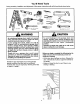
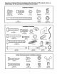
You'll Need Tools During assembly, installation and adjustment of the opener, instructions will call for hand tools shown below. k..'.k _:s- "-'-1v. ¢.=.11.,T, r•rt .:.,tt: ._.11: F..,.:.;. r..I -"=re. Fcl-- ".1_',T '1' '; '_' -".l_.::z .'4_.= _'.,.-.'v.r:t WARNING An unbalanced garage door might not reverse when required and someone under the door could be seriously injured or killed. If your garage door binds, sticks or is out of balance, call for professional garage door service.
Before you begin, survey your garage area to see whether any of the conditions below apply to your installation. FINISHED CEILING Support bracket & is required. See page 17. Horizontal arid vertical retnlorcement is needed for lightweight garage doors (fiberglass, steel, aluminum, dOOr with glass panels, etc.). See page 24 lot details. Header Wall Extension Floor mustbe level aerosswldthotdoor.
::::::::::::::::::::::::::::::::::::::::::::::::::::::::::::::::::::::::::::::::::::::::::::::::::::::::::::::::::::::::::::::::::::::: One-P ece Door without Track Before you begin, survey your garage area to see whether any of the conditions below apply tO your installation, FINISHED CEILI Suppo_ bracket _ hardw&faSlsen_lguired q • See page 17, II _ __....._-_-Safety Safety _ K\\_I Door ' Gap between lleor and bottom Sensor Reversln of door must not exceed 1/4".
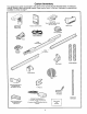
Carton Inventory Your garage door opener is packaged in two cartons which contain all parts illustrated below. If anything is missing, carefully check the packing material. Parts may be "stuck" in the foam. Hardware for assembly and installation is shown on page 7.
Separate all hardware from the packages in the rail carton and the opener shown below, for the assembly and installation procedures.
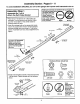
Assembly Section: Pages 8 - 11 To avoid installation Assembly difficulties, do not run the garage door opener until instructed Make sure bolt necks are seated in the square holes and rails are aligned before you tighten lock nuts. (See right and wrong views). Improper assembly can cause jerky trolley operation, noise and/or nuisance door reversals. Right Wrong Step 1 Assemble the T-rail & Attach the Belt Pulley Bracket • Place the 3 T-rail sections on a flat surface for assembly.
Assembly Step 2 Install the Trolley on the T-rail • As a temporary stop, insert a screwdriver into the hole in the front end of the T-rail. • Slide the trolley assembly along the rail to the screwdriver stop. If trolley hits against any nuts on the T-rail, the bolts and nuts were attached from the wrong side and must be repositioned. Review Step 1. Hex Screw 5/16"-18x7/8" Trolley Stop Hole Temporary Stop Screwdriver \ .
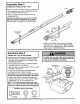
Assembly Install the Belt Step 4 I & Set the Belt Tension I 1. Drop the notched side of the trolley clip into the retaining slot on top of the trolley. (Figure 1) 2. Grasp the clip connector at the end of the belt and slip it through the belt //f_'_,'_ pulley bracket from behind, around Figure 1 the pulley and toward the trolley. _,,/_ 3. Fasten the belt clip connector to the _/LI .....
Assembly Step 5 Attach the Belt Cap Retainer To attach the belt cap retainer: Hex Screws #8x3/8" Position the belt cap retainer over the opener sprocket so the two holes in cap align with the two holes in mounting plate. Attach with 8x3/8" hex screws provided. _---_-,_ _t_=_'_l _ - Belt Cap Retainer Opener Sprocket Plate Hardware Shown Actual Size Hex Screw #8x3/8' You have now finished warnings assembling before proceeding your garage to the installation door opener.
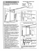
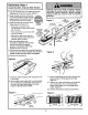
Installation Installation Section: Pages 12 - 27 Step 1 Determine Header Bracket Location If the header bracket is not rigidly fastened to a structural support on the header wall or ceiling, the safety reverse system may not work properly (see page 30). The door might not reverse when required, and could cause serious injury or death. Installation procedures vary according to garage door types. Follow the instructions which apply to your door.
::::: :: _.:'. -:.-.+:':':" :_;:':':':::'+"""":":':"""::""'-':::: ::: :::;:::::.-..:':1;:':'i"i:i $i:i:"i:i:i:_:'::_"" ":!:i:i_i_ i:_ ?::_ _"_ Read the Safety instructions on page 12. They also apply to doors without Unfinished tracks. -- Header Wall Vertical Centedine 2X4 • Close the door and mark the inside vertical centerline of your garage door. Extend the line onto the header wall above door. If headroom clearance is minimal, you can install the header bracket on the ceiling. See page 14.
Installation Install You can attach the header bracket either to the wall above the garage door, or to the ceiling. Follow the instructions which will work best for your particular requirements. Step 2 the Header Bracket Fasten the Header Bracket to the Wall • Mark either set of bracket holes (do not use the holes designated for ceiling mount). Drill 3/16" pilot holes and fasten the bracket securely to a structural support with the hardware provided.
Installation Attach Step 3 the T-rail to the Header -- I Bracket I • Position the opener on the garage floor below the header bracket. Use packing material as a protective base. Header Wall Header Bracket If the door spring is in the way you'll need help. Have someone hold the opener securely on a temporary support to allow the T-rail to clear the spring. Bracket • Position the belt pulley bracket against the header bracket. • Align the bracket holes and join with a clevis pin as shown.
Installation Position Step 4 _i_i_i_i_i_i_i _i_i_i_!_!_ i_i_i_i_i_i_i_i_!_i_i_i_ __i • _ _ • •÷ _ • _ _i_:i_!_i_i_i_:_::_::_::_:_:: _ ::_::i_!_'_i_i_ _:_:_ the Opener Follow instructions type as illustrated. TO prevent damage to steel, aluminum, fiberglass or glass panel doors, do not rest the opener on the door without using a 2x4. which apply to your door A 2x4 laid flat is convenient for setting an ideal door-to-T-rail distance. 2x4 Laid Flat T-rail Raise the opener onto a stepladder.
:::::::::::::::::::::::::::::::::::::::::::::::::::::::::::::::::::::::::::::::::::::::::::::::::::::::::::::::::::::::::::::::::::::::::::::::::::::::::::::::::::::::::::::::: ::::::::::::::::::::::::: Installation Step 5 I I Hang the Opener ::::::::::::::::::::::::::::::::::::::::::::::::::_-:_,3"_,_:-_;_;:;_:_;_ :: :::_:_:_:_::::_:::::::_:_L:" The opener could fall and injure someone if it is not properly secured. Fasten the opener securely to structural supports of the garage.
Installation ::::::::::::::::::::::::::::::::::::::... .:u::::::t:::: :::::::::::::::::::::::::::::::::::::::::::::: ::::::::::::::::::::::: Step 6 Install the Premium Control : :::::::::::::::::::::::::::::::::::::: ":t::_:::::_:: : -:+ :;+..:_. .... : ::::5::::_; :::::5::;::::_:: _... .+:.:,>:,:,:.;,_:+:>:<.::+:: Console IIITI" Do not connect to live electrical wiring, Connect only to 24 Volt low voltage wires.
6.Attachthe User Safety Instruction label to the wall near the door control, and the Maintenance Instruction label in a prominent location on the inside of the garage door. Do NOT connect the power and operate the opener at this time. The trolley will travel to the full open position but will not return to the close position until the sensor beam is connected and properly aligned, See Safety Reversing Sensor instructions beginning on page 21. Page 32 explains how to use the door control.
Installation Electrical Step 9 I I Requirements To prevent electrocution or fire, installation and wiring must be in compliance with local electrical and building codes. To reduce the risk of electric shock, your garage door opener has a grounding type plug with a third ]rounding pin. This plug will onlyfit into a grounding type outlet. Do NOTuse an extension cord, 2-wire adapter, or change the plug in any way to make it fit your outlet.
The Safety Reversing System Information you'll need before you begin the installation The safety reversing sensor must be connected and aligned correctly before the garage door opener will move in the down direction. This is a required safety device and cannot be disabled, Installation procedures and one-piece doors. of the safety reversing :::::::::::::::::::::::: _ :::.:::_-" .._.._.._....._... ::::::::::::::::::::::::::::::::::::::::: : :.:5.:_::_:: sensor. :.:.;_.._..-...-......-..;_::_.....L:.-.
Installation Install Step 10 I the Safety Reversing I Sensor Figure 2 Figures 2 and 3 show assembly of brackets and "C" wrap based on the recommended installation of the sensors as shown on page 21. Mounting Bracket With Square Holes However, Figures 4 and 5 are variations which may fit your installation requirements better.
• Center each sensor unit in a "C" wrap with lenses pointing toward each other across the door (see Figure 6). Figure 6 IndLcator • Secure sensors with the hardware shown. Finger tighten the wing nut on the receiving eye to allow for final adjustment. Securely tighten the sending eye wing nut. Ught 1/4-20 X 1-1/2' HexBolt • Run the wires from both sensors to the opener. Use insulated staples to secure wire to wall and ceiling. Trouble Shooting • Strip 1/4" of insulation from each set of wires.
Installation Fasten Step 11 Door Bracket Follow instructions which apply to your door type as illustrated below or on page 25. A horizontal brace should be long enough to be secured to 2 vertical supports. A vertical brace should cover the height of the top panel. The illustration shows one piece of angle iron as the horizontal brace. For the vertical brace, 2 pieces of angle iron are used to create a "U"-shaped support.
_!:_:_::: Please read and comply They apply to one-piece __:_:__";:;_"::: ::::_i_ :¸:::::::I!_!_!I!_:_!I!_!_!_; _i:'::!_!i:_:_ii:_:i::'::i:i:_::''_.:_:i::':'_ _:i:_:i:_:_:i E"":"__:_$_:i:F.:i:_::_:':i:_::i: _i:i:_:_i with the warnings doors also. Header Wall -- and reinforcement instructions on page 24. Finished Ceiling -- 2x4 Support Header Bracket Bracket Horizontal and vertical reinforcement is needed for lightweight garage doors (fiberglass, aluminum, steel, door with glass panel, etc.).
Installation Connect Step 12 Door Arm to Trolley Follow instructions which apply to your door type as illustrated below and on page 27. Make sure garage door is fully closed. Pull the emergency release handle to disconnect the outer trolley from the inner trolley. Slide the outer trolley back (away from the door) about 2" as shown in Figures 1, 2 and 3. Figure 1: Figure 2: • Fasten straight door arm section to outer trolley with the 5/16"xl" clevis pin. Secure the connection with a ring fastener.
Assemble the Door Arm: Door • Fasten the straight and curved door arm sections together to the longest possible length, with a 2 or 3 hole overlap, Ring Bracket _,_---._,._Ji_ Fastener Loc_ Washers 5/16" • With the door closed, connect the straight door arm section to the door bracket with the 5/16"xl -1/4" clevis pin. Nuts 5/16 -18 Screw • Secure with a ring fastener. Door Arm On one-piece doors, before connecting the door arm to the trolley the travel limits must be adjusted.
Adjustment Section: Pages 28 - 30 Adjustment Step 1 Adjust the UP and DOWN Limits Do not make any limit adjustments until the safety reversing sensors are completely installed. Improper adjustment of the travel limits will interfere with the proper operation of the safety reverse system. The door might not reverse properly when required and could seriously injure or kill someone under it. Test the safety reverse system following all adjustments to the travel limits. See page 30.
Adjustment Adjust Step 2 I I the Force Too much force on the door will interfere with the proper operation of the safety reverse system. The door might not reverse properly when required and could seriously injure or kill someone under it. Do not increase the force beyond the minimum amount required to close the door. Do not use the force adjustments to compensate for a binding or sticking garage door. Test the safety reverse system following all adjustments to force levels. See page 30.
Adjustment Step 3 Test The Safety Reversing Sensor I • Press the remote control push button to open the door. • Place the opener carton in the path of the door. • Press the remote control push button to close the door. The door will not move more than an inch, and the opener light(s) will flash. Professional service is required if the opener closes the door when the safety reversing sensor is obstructed.
IMPORTANT SAFETY INSTRUCTIONS To reduce the risk of severe injury or death to persons: 1. READ AND FOLLOW ALL INSTRUCTIONS. 5. If possible, use the emergency release only when the door is in a closed position. Caution should be taken whenever the disconnect cord is actuated with the door open. Weak or broken springs may cause the door to fall rapidly, causing injury or death to persons. 6. KEEP GARAGE DOORS PROPERLY BALANCED. See page 3.
Operation of Your Opener Activate the opener with any of the following: • The Remote Control: Hold push button clown until the door starts to move. • The Door Control: Hold push button down until the door starts to move. • Weak or broken springs could allow an open door to fall (either rapidly or unexpectedly), resulting in serious injury, death or property damage. If possible, use the emergency release rope and handle onlywhen the door is fully closed.
Receiver and Remote Control Programming 1 To comply with FCC rules, adjustment or modifications of this receiver / and/or transmitter are prohibited, except for changing the code setting or replacing the battery. THERE ARE NO OTHER USER SERF[CEABLE Your garage door opener receiver and remote control have been pre-set at the factory. The door will open when you press the LARGE remote control push button.
Having a Problem? Situation Probable Cause and Solution The opener doesn't operate from either the Door Control or the remote control: 1. Does the opener have electric power?. Plug a lamp intothe outlet. If it doesn't light, check the fuse box or the circuit breaker. (Some outlets are controlled by a door switch.) 2. Have you disabled all door locks? Review installation instruction wamings on Page 11. 3. Is there a build-up of ice or snow under the door? The door may be frozen to the ground.
Having a Problem? Situation The door opens but won't close: Probable (continued) Cause & Solution 1. If the opener lights blink, check the safety reversing sensor. See page 23. 2. If the opener lights do not I_link and it is a new installation, check the down force. See Adjustment Step 2, page 29. For an existing installation, see below. Repeat the safety reverse test after the adjustment is complete• The door reverses for no apparent reason and opener lights don? blink: 1.
Repair Parts Rail Assembly 4 Parts 3 6 KEY NO. 4 1 2 3 4 5 6 7 8 9 PART NO. DESCRIPTION 1A995 41 B3869 1B3117 183Bl10 Master link kit Complete trolley assembly T-rail- center section T-rail - and section 41A3588-1 41A3589-12 83A4 41B4103 109B33 Belt pulley bracket Full belt assembly Rail grease Tension assembly (Spring/Trolley Nut) Trolley Clip NOT SHOWN Rail assembly hardware kit (see page 7). 41A3534 Installation Parts 139.53681 1 KEY PART NO. NO.
Repair Parts Opener Assembly Parts , ' -_- _-"---'-"_ ' 3 ; _3 5 _2 16 IL_"11 _._ j18 7 = ..,, 19 14
Accessories Sears offers many useful accessories for your garage door opener. They ere illustrated Sears model numbers and descriptions. i139.53702 f 139.53681 Emergency Key Release: Requiredfor a garage with NO access door. Enables homeowner to open garage door manually from outside by disengaging trolley. Outdoor Key Switch: SECURITY+ Keyless Entry: Enables homeowner to operate garage door opener from outside by entering a password.Also can add a temporary password for visitorsor service persons.
Index Access Door/Outside Key Release Accessory ............................................................................................... 4, 5 Belt Tension ................................................................................................................................................. 4, 5, 11 Electrical Safety Warnings ........................................................................................................................
For professional installation Call 24 hours a day, 7 days a week 1-8OO-865-6500 For the repair or replacement parts you need Call 7 am - 7 pro, 7 days a week 1-8OO-366-PART (1-800-366-7278) For in-home major brand repair service Call 24 hours a day, 7 days a week 1-8OO-4-REPAIR (1-800-473-7247) For the location of a Sears Repair Service Center Call 24 hours a day, 7 days a week in your area 1-800-488-1222 For information on purchasing a Sears Maintenance Agreement or to inquire about an existing Agree