Owner’s Manual/Manual Del Propietario GARAGE DOOR OPENER ABRIDOR DE PUERTA DE COCHERA For Residential Use Only/Sólo para uso residencial Model/Modelo • 139.53906D Fasten the manual near the garage door after installation. Periodic checks of the opener are required to ensure safe operation. Leer y seguir todas las reglas de seguridad y las instrucciones de operación antes de usar este producto por primera vez. Guardar este manual cerca de la puerta de la cochera.
TABLE OF CONTENTS Introduction 2-7 Adjustment Safety symbol review and signal word review. . . . . . . . . . . . . . . . 2 Preparing your garage door . . . . . . . . . . . . . . . . . . . . . . . . . . . . . 3 Tools needed. . . . . . . . . . . . . . . . . . . . . . . . . . . . . . . . . . . . . . . . . 3 Planning . . . . . . . . . . . . . . . . . . . . . . . . . . . . . . . . . . . . . . . . . . 4-5 Carton inventory . . . . . . . . . . . . . . . . . . . . . . . . . . . . . . . . . . . . . .
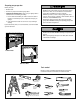
Preparing your garage door Before you begin: • Disable locks. • Remove any ropes connected to garage door. • Complete the following test to make sure your garage door is balanced and is not sticking or binding: 1. Lift the door about halfway as shown. Release the door. If balanced, it should stay in place, supported entirely by its springs. 2. Raise and lower the door to see if there is any binding or sticking. If your door binds, sticks, or is out of balance, call a trained door systems technician.
Planning • Do you have an access door in addition to the garage door? If not, Model 139.18752 Emergency Key Release is required. See Accessories page. • Look at the garage door where it meets the floor. Any gap between the floor and the bottom of the door must not exceed 1/4" (6 mm). Otherwise, the safety reversal system may not work properly. See Adjustment Step 3. Floor or door should be repaired. Identify the type and height of your garage door.
Planning (Continued) ONE-PIECE DOOR INSTALLATIONS • Generally, a one-piece door does not require reinforcement. If your door is lightweight, refer to the information relating to sectional doors in Installation Step 12. • Depending on your door’s construction, you may need additional mounting hardware for the door bracket (Step 12).
Carton Inventory Your garage door opener is packaged in one carton which contains the motor unit and all parts illustrated below. Accessories will depend on the model purchased. If anything is missing, carefully check the packing material. Parts may be stuck in the foam. Hardware for assembly and installation is shown on the next page. Save the carton and packing material until installation and adjustment is complete.
Hardware Inventory Separate all hardware and group as shown below for the assembly and installation procedures.
ASSEMBLY STEP 1 Assemble the Rail and Install the Trolley To prevent INJURY from pinching, keep hands and fingers away from the joints while assembling the rail. To avoid installation difficulties, do not run the garage door opener until instructed to do so. The front rail has a cut out “window” at the door end (see illustration). The hole above this window is larger on the top of the rail than on the bottom. A smaller hole 3-1/2" (8.9 cm) away is close to the rail edge.
ASSEMBLY STEP 2 Fasten the Rail to the Motor Unit To avoid SERIOUS damage to garage door opener, use ONLY those bolts/fasteners mounted in the top of the opener. • Insert a 1/4"-20x1-3/4" bolt into the cover protection bolt hole on the back end of the rail as shown. Tighten securely with a 1/4"-20 lock nut. DO NOT overtighten. • Remove the two bolts from the top of the motor unit. • Place the “U” bracket, flat side down, on the motor unit and align the bracket holes with the bolt holes.
ASSEMBLY STEP 4 Install the Belt and Attach the Belt Cap Retainer To avoid possible SERIOUS INJURY to fingers from moving garage door opener: • ALWAYS keep hand clear of belt pulley while operating opener. • Securely attach belt pulley cover BEFORE operating. 1. Pull the belt around the idler pulley and toward the trolley. The ribbed side must contact the pulley. 2. Hook the trolley connector into the retaining slot on the trolley as shown. 3.
ASSEMBLY STEP 5 Set the Tension • Insert a screwdriver tip into one of the nut ring slots and brace it firmly against the trolley. • Place a 7/16" open end wrench on the square end. Rotate the nut about 1/4 turn until the spring releases and snaps the nut ring against the trolley. This sets the spring to optimum belt tension. Nut Ring Slot You have now finished assembling your garage door opener. Please read the following warnings before proceeding to the installation section.
INSTALLATION STEP 1 Unfinished Ceiling Determine the Header Bracket Location OPTIONAL CEILING MOUNT FOR HEADER BRACKET Header Wall To prevent possible SERIOUS INJURY or DEATH: • Header bracket MUST be RIGIDLY fastened to structural support on header wall or ceiling, otherwise garage door might NOT reverse when required. DO NOT install header bracket over drywall. • Concrete anchors MUST be used if mounting header bracket or 2x4 into masonry.
INSTALLATION STEP 2 Install the Header Bracket You can attach the header bracket either to the wall above the garage door, or to the ceiling. Follow the instructions which will work best for your particular requirements. DO NOT install the header bracket over drywall. If installing into masonry, use concrete anchors (not provided).
INSTALLATION STEP 3 Attach the Rail to the Header Bracket NOTE: (Optional) With some existing installations, you may re-use the old header bracket with the two plastic spacers included in the hardware bag. Place the spacers inside the bracket on each side of the rail, as illustrated. • Position the opener on the garage floor below the header bracket. Use packing material as a protective base. NOTE: If the door spring is in the way, you will need help.
INSTALLATION STEP 4 Position the Opener To prevent damage to garage door, rest garage door opener rail on 2x4 placed on top section of door. Follow instructions which apply to your door type as illustrated. SECTIONAL DOOR OR ONE-PIECE DOOR WITH TRACK A 2x4 laid flat is convenient for setting an ideal door-to-rail distance. • Remove foam packaging. • Raise the opener onto a stepladder. You will need help at this point if the ladder is not tall enough.
INSTALLATION STEP 5 Hang the Opener To avoid possible SERIOUS INJURY from a falling garage door opener, fasten it SECURELY to structural supports of the garage. Concrete anchors MUST be used if installing ANY brackets into masonry. Three representative installations are shown. Yours may be different. Hanging brackets should be angled (Figure 1) to provide rigid support. On finished ceilings (Figures 2 and 3), attach a sturdy metal bracket to structural supports before installing the opener.
INSTALLATION STEP 6 Install the Door Control To prevent possible SERIOUS INJURY or DEATH from electrocution: • Disconnect ALL electric and battery power BEFORE performing ANY service or maintenance. • Connect ONLY to 24 VOLT low voltage wires. To prevent possible SERIOUS INJURY or DEATH from a closing garage door: • Install door control within sight of garage door, out of reach of children at a minimum height of 5 feet (1.5 m), and away from ALL moving parts of door.
INSTALLATION STEP 7 Install the Battery ALWAYS wear protective gloves and eye protection when changing the battery or working around the battery compartment. • Make sure motor unit is unplugged. • Using a Phillips head screwdriver, remove the battery cover on the motor unit. • Partially insert new battery into motor unit with terminals facing out. • Connect red (+) and black (-) wires from motor unit to corresponding terminals on battery. • Verify the battery wires are seated in the channel.
INSTALLATION STEP 9 Attach the Emergency Release Rope and Handle To prevent possible SERIOUS INJURY or DEATH from a falling garage door: • If possible, use emergency release handle to disengage trolley ONLY when garage door is CLOSED. Weak or broken springs or unbalanced door could result in an open door falling rapidly and/or unexpectedly. • NEVER use emergency release handle unless garage doorway is clear of persons and obstructions. • NEVER use handle to pull door open or closed.
INSTALLATION STEP 11 Install The Protector System® Be sure power is not connected to the garage door opener BEFORE installing the safety reversing sensor. To prevent SERIOUS INJURY or DEATH from a closing garage door: • Correctly connect and align the safety reversing sensor. This required safety device MUST NOT be disabled. • Install the safety reversing sensor so beam is NO HIGHER than 6" (15 cm) above garage floor.
INSTALLING THE BRACKETS Be sure power to the opener is disconnected. Install and align the brackets so the sensors will face each other across the garage door, with the beam no higher than 6" (15 cm) above the floor. They may be installed in one of three ways, as follows. Garage door track installation (preferred): • Slip the curved arms over the rounded edge of each door track, with the curved arms facing the door. Snap into place against the side of the track.
MOUNTING AND WIRING THE SAFETY REVERSING SENSORS • Slide a 1/4"-20x1/2" carriage bolt head into the slot on each sensor. Use wing nuts to fasten sensors to brackets, with lenses pointing toward each other across the door. Be sure the lens is not obstructed by a bracket extension (Figure 5). • Finger tighten the wing nuts. • Run the wires from both sensors to the opener. Use insulated staples to secure wire to wall and ceiling. • Strip 7/16" (11 mm) of insulation from each set of wires.
INSTALLATION STEP 12 Fasten the Door Bracket Fiberglass, aluminum or lightweight steel garage doors WILL REQUIRE reinforcement BEFORE installation of door bracket. Contact your door manufacturer for reinforcement kit. Follow instructions which apply to your door type as illustrated below or on the following page. A horizontal reinforcement brace should be long enough to be secured to two vertical supports. A vertical reinforcement brace should cover the height of the top panel.
ONE-PIECE DOORS Please read and comply with the warnings and reinforcement instructions on the previous page. They apply to one-piece doors also. • Center the door bracket on the top of the door, in line with the header bracket as shown. Mark either the left and right, or the top and bottom holes. • Drill 5/16" pilot holes and fasten the bracket with hardware supplied.
INSTALLATION STEP 13 Pulley Connect Door Arm to Trolley 8" (20 cm) min. Follow instructions which apply to your door type as illustrated below and on the following page. SECTIONAL DOORS ONLY Make sure garage door is fully closed. Pull the emergency release handle to disconnect the outer trolley from the inner trolley. Slide the outer trolley back (away from the pulley) about 8" (20 cm) (Figures 1, 2 and 3). Figure 1: • Fasten straight door arm section to outer trolley with the 5/16"x1" clevis pin.
ALL ONE-PIECE DOORS 1. Assemble the Door Arm:, Figure 5: IMPORTANT: The groove on the straight door arm MUST face away from the curved door arm. • Fasten the straight and curved door arm sections together to the longest possible length (with a 2 or 3 hole overlap) (Figure 4). • Make sure the garage door is fully closed. Connect the straight door arm section to the door bracket with the 5/16"x1-1/4" clevis pin. • Secure with a ring fastener.
ADJUSTMENT STEP 1 Program the Travel Limits Without a properly installed safety reversal system, persons (particularly small children) could be SERIOUSLY INJURED or KILLED by a closing garage door. • Incorrect adjustment of garage door travel limits will interfere with proper operation of safety reversal system. • NEVER use force adjustments to compensate for a binding or sticking garage door. • After ANY adjustments are made, the safety reversal system MUST be tested.
ADJUSTMENT STEP 2 Set the Force Without a properly installed safety reversal system, persons (particularly small children) could be SERIOUSLY INJURED or KILLED by a closing garage door. • Too much force on garage door will interfere with proper operation of safety reversal system. • NEVER use force adjustments to compensate for a binding or sticking garage door. • After ANY adjustments are made, the safety reversal system MUST be tested. Door MUST reverse on contact with 1-1/2" (3.
ADJUSTMENT STEP 3 Test the Safety Reversal System Without a properly installed safety reversal system, persons (particularly small children) could be SERIOUSLY INJURED or KILLED by a closing garage door. • Safety reversal system MUST be tested every month. • After ANY adjustments are made, the safety reversal system MUST be tested. Door MUST reverse on contact with 1-1/2" high (3.8 cm) object (or 2x4 laid flat) on the floor. TEST • With the door fully open, place a 1-1/2" (3.
WARNING OPERATION IMPORTANT SAFETY INSTRUCTIONS WARNING To reduce the risk of SEVERE INJURY or DEATH: 9. If one control (force or travel limits) is adjusted, the other control may also need adjustment. 10. After ANY adjustments are made, the safety reversal system MUST be tested. 11. Safety reversal system MUST be tested every month. Garage door MUST reverse on contact with 1-1/2" (3.8 cm) high object (or a 2x4 laid flat) on the floor.
USING THE WALL-MOUNTED DOOR CONTROL Press the push button to open or close the door. Press again to reverse the door during the closing cycle or to stop the door while it’s opening. To Open the Door Manually To prevent possible SERIOUS INJURY or DEATH from a falling garage door: • If possible, use emergency release handle to disengage trolley ONLY when garage door is CLOSED. Weak or broken springs or unbalanced door could result in an open door falling rapidly and/or unexpectedly.
THE REMOTE CONTROL BATTERY Care of Your Opener MAINTENANCE SCHEDULE Once a Month • Manually operate door. If it is unbalanced or binding, call a trained door systems technician. • Check to be sure door opens and closes fully. Adjust limits and/ or force if necessary (see pages 27 and 28). • Repeat the safety reverse test. Make any necessary adjustments (See Adjustment Step 3). Once a Year • Oil door rollers, bearings and hinges. The opener does not require additional lubrication.
Battery Backup OPERATING INSTRUCTIONS 1. Test the installed battery with the motor unit. To test the battery, disconnect the motor unit power cord from the electrical outlet. • A solid orange LED indicates the battery is operating on battery power. • A flashing orange LED with beep indicates the unit is operating on battery power and that the battery charge is low. • To test the battery is functioning properly, open and close the garage door.
Having a Problem (Troubleshooting) NOTE: Always unplug battery prior to troubleshooting. 1. My door will not close and the light bulbs blink on my motor unit: The safety reversing sensor must be connected and aligned correctly before the garage door opener will move in the down direction. • Verify the safety reversing sensors are properly installed, aligned and free of any obstructions. Refer to Installation Step 11: Install The Protector System ® .
Bell Wire Installed Installed Safety SafetyReversing Reversing Sensor Sensor Safety Reversing Sensor “Learn” Button LED or Diagnostic LED “Learn” Button Your garage door opener is programmed with self-diagnostic capabilities. The “Learn” button/diagnostic LED will flash a number of times then pause signifying it has found a potential issue. Consult Diagnostic Chart below. Diagnostic Chart 1 FLASH Safety reversing sensors wire open (broken or disconnected).
PROGRAMMING NOTICE: If this Security✚® garage door opener is operated with a non-rolling code transmitter, the technical measure in the receiver of the garage door opener, which provides security against code-theft devices, will be circumvented. The owner of the copyright in the garage door opener does not authorize the purchaser or supplier of the non-rolling code transmitter to circumvent that technical measure.
To Add, Reprogram or Change a Keyless Entry PIN NOTE: Your new Keyless Entry must be programmed to operate your garage door opener. USING THE “LEARN” BUTTON To change an existing, known PIN If the existing PIN is known, it may be changed by one person without using a ladder. 1. Press the four buttons for the present PIN, then press and hold the # button. The opener light will blink twice. Release the # button. 2. Press the new 4-digit PIN you have chosen, then press ENTER.
REPAIR PARTS Rail Assembly Parts 2 1 3 4 6 KEY NO. 5 1 2 3 4 5 6 7 7 PART NO. 4A1008 41C5141-2 41A5665-2 41B4103 144C54 41A5250 12D598-1 183A163 Installation Parts Master link kit Complete trolley assembly Complete rail Spring trolley nut Idler pulley Full belt assembly “U” bracket NOT SHOWN Wear pads 2 KEY NO. 3 1 1 4 7 5 6 10 8 11 2 3 4 5 6 7 8 9 10 11 12 9 13 14 13 DESCRIPTION 12 PART NO.
Motor Unit Assembly Parts 2 1 3 10 11 7 4 5 8 6 10 9 KEY NO. 1 2 3 4 5 6 7 PART NO. 41A537 41B4245 41B4375-3 41A6281 41D843 41DB102-2 41A6268 DESCRIPTION Belt cap and pulley Line cord Terminal block with screws Wire harness kit Motor with travel module Receiver logic assembly End panel with battery door and screw 39 KEY NO. PART NO.
NOTES 40
ACCESSORIES 139.53702 139.53728 139.53729 Emergency Key release: Required for a garage with NO access door. Enables homeowner to open garage door manually from outside by disengaging trolley. 8 Foot (2.4 m) Rail Extension: OR 10 Foot (3 m) Rail Extension: To allow an 8 foot (2.4 m) or a 10 foot (3 m) door to open fully. 139.53753 SECURITY✚® 3-Function Remote Control: Includes visor clip. 139.53752 SECURITY✚® Compact 3-Function Remote Control: With loop for attaching key ring. 139.
A A CONTENIDO Introducción 2-7 Ajustes Revisión de los símbolos y términos de seguridad . . . . . . . . . . . . . . . . . 2 Preparación de la puerta de su cochera . . . . . . . . . . . . . . . . . . . . . . . . . 3 Herramientas necesarias. . . . . . . . . . . . . . . . . . . . . . . . . . . . . . . . . . . . . 3 Planificación . . . . . . . . . . . . . . . . . . . . . . . . . . . . . . . . . . . . . . . . . . . . .4-5 Inventario de la caja de cartón . . . . . . . . . . . . . . . . . . . . . . . . . . . .
ADVERTENCIA ADVERTENCIA Preparación de la puerta de su cochera Antes de comenzar: • Quite los seguros. • Retire cualquier cuerda o cable que esté conectado a la puerta. • Haga la siguiente prueba con su puerta para verificar que esté balanceada y que no se atore ni se pandee: 1. Levante la puerta hasta la mitad de su recorrido como se muestra. Suelte la puerta. Si está balanceada, deberá mantenerse en esa posición con sólo el soporte de los resortes. 2.
Planificación Identifique la altura y el tipo de su puerta de cochera. Revise el área de su cochera y observe si alguna de las siguientes instalaciones corresponden a la suya. A veces se requieren materiales adicionales, así que tal vez sea conveniente tener esta hoja y las ilustraciones correspondientes a mano cuando inicie la instalación de su abridor. Dependiendo de sus necesidades individuales, es posible que en algunos casos vaya a necesitar materiales o herramientas que no se incluyen con este producto.
Planificación (continúa) ADVERTENCIA INSTALACIÓN CON PUERTAS DE UNA SOLA PIEZA • Generalmente una puerta de una sola pieza no requiere refuerzos adicionales. Si usted tiene una puerta de material liviano y quiere reforzarla, consulte la información respecto a puertas seccionales, contenida en Instalación, Paso 12. • Dependiendo del diseño de su puerta, tal vez necesite piezas de montaje adicionales para la ménsula de la puerta (Paso 12).
Inventario de la caja de cartón Su abridor viene empacado en una caja de cartón que contiene el motor y las piezas que se muestran en la siguiente ilustración. Tome nota de que los accesorios dependerán del modelo que haya comprado. Si falta alguna pieza, revise con cuidado el material de empaque ya que en ocasiones las piezas se atoran en el mismo. Toda la tornillería y las piezas necesarias para el montaje e instalación de su puerta se ilustran en la siguiente página.
Inventario de piezas Antes de la instalación, organice todas las piezas en grupos como se muestra en la siguiente ilustración. TORNILLERÍA Y PIEZAS PARA EL MONTAJE Resorte / tuerca del trole (1) Tuerca de 1/4-20 de pulg. (2) Arandela de 3/8 de pulg. (1) Tuerca de 3/8 de pulg. (1) Perno de 1/4-20x1-3/4 de pulg. (2) Enlace maestro (2) Perno loco (1) Flecha roscada del trole (1) TORNILLERÍA Y PIEZAS PARA LA INSTALACIÓN Perno de coche de 1/420x1/2 de pulg. (2) Tuerca de mariposa 1/4-20 de pulg.
MONTAJE, PASO 1 PRECAUCIÓN Monte el riel e instale el trole Para evitar QUE SE PELLIZQUE, conserve los manos y dedos lejos de las juntas cuando monte el reil. No encienda ni use el abridor hasta que llegue al paso de la instalación correspondiente, de otra manera corre el riesgo de complicar el proceso de instalación. El riel delantero tiene una “ventana” cortada en el extremo de la puerta (vea la ilustración).
MONTAJE, PASO 2 PRECAUCIÓN Fije el riel a la unidad del motor Use SÓLO el perno y la tuerca que vienen montados en la parte superior del abridor para evitar que el abridor de la puerta de cochera se dañe SERIAMENTE. • Coloque un perno de 1/4-20x1-3/4 de pulg. dentro del orificio de la cubierta de protección que se encuentra en el extremo posterior del riel, como se indica en la ilustración. Apriete bien el perno con tuerca de1/4-20 de pulg. NO ajuste demasiado la tuerca.
MONTAJE, PASO 4 ADVERTENCIA Instale la banda y sujete el retén de la cubierta de la banda Para evitar posibles LESIONES GRAVES en los dedos causadas por las partes móviles del abridor de puerta de cochera: • Aparte SIEMPRE la mano de la polea de la correa mientras haga funcionar el abridor. • Conecte bien la cubierta de la polea de la correa ANTES de hacer funcionar. 1. Jale la banda alrededor de la polea loca hacia el trole. El lado acanalado debe estar en contacto con la polea. 2.
MONTAJE, PASO 5 Fije la tensión de la banda • Ponga la punta de un destornillador dentro de una de las ranuras del anillo de la tuerca y sujételo firmemente contra el trole. • Ponga una llave abierta de 7/16 de pulg en el extremo cuadrado. Dé vuelta a la tuerca más o menos un 1/4 de su giro completo hasta que se suelte el resorte y el anillo de la tuerca quede contra el trole. Esto fija el resorte a la tensión óptima de la banda.
INSTALACIÓN, PASO 1 Determine dónde va a instalar la ménsula del cabezal Cielo raso sin acabado INSTALACIÓN OPCIONAL DE LA MÉNSULA DEL CABEZAL EN EL CIELO RASO ADVERTENCIA Para evitar una posible LESIÓN GRAVE o INCLUSO LA MUERTE: • La ménsula del cabezal DEBE quedar RÍGIDAMENTE sujeta al soporte estructural en la pared delantera o en el cielo raso, de no ser así es posible que la puerta de la cochera NO retroceda cuando se requiera. NO instale la ménsula del cabezal en muros falsos.
INSTALACIÓN, PASO 2 Montaje en la pared Instale la ménsula del cabezal La ménsula del cabezal se puede fijar a la pared justo por encima de la puerta de la cochera o en el cielo raso. Siga las instrucciones que sean más adecuadas para su cochera. No instale la ménsula del cabezal en un muro falso. Si va a fijar la ménsula del cabezal a ladrillo o mampostería, asegúrese de utilizar sujetadores de cemento (no se incluyen).
INSTALACIÓN, PASO 3 Coloque el riel en la ménsula del cabezal NOTA: (Opcional) Con algunas instalaciones anteriores puede reutilizar la antigua ménsula del cabezal con los dos espaciadores de plástico que se incluyen en la bolsa de componentes. Coloque los espaciadores en el interior de la ménsula, a cada lado del riel, tal y como se muestra en la ilustración. • Coloque el abridor sobre el piso de la cochera debajo de la ménsula del cabezal. Use el material de empaque como base para protegerlo.
INSTALACIÓN, PASO 4 PRECAUCIÓN Coloque el abridor en posición Para evitar que la puerta de cochera sufra daños, apoye el riel del abridor de la misma sobre un pedazo de madera de 5x10 cm (2x4 pulg.) colocado en la sección superior de la puerta. Siga las instrucciones correspondientes al tipo de puerta de su cochera, como se muestra en la ilustración. PUERTA SECCIONAL O PUERTA DE UNA SOLA PIEZA CON CARRIL Un pedazo de madera de 5x10 cm (2x4 pulg.
INSTALACIÓN, PASO 5 ADVERTENCIA Cuelgue el abridor Para evitar la posibilidad de una LESIÓN GRAVE si se cae el abridor de la puerta de cochera, sujételo FIRMEMENTE a los soportes estructurales de la cochera. Se DEBEN usar sujetadores para concreto si alguna de las ménsulas se va a instalar en mampostería. Aquí se muestran tres ejemplos distintos para la instalación; sin embargo, es posible que su cochera no concuerde con ninguno de ellos.
ADVERTENCIA INSTALACIÓN, PASO 6 ADVERTENCIA Instale la control de la puerta Para evitar la posibilidad de una LESIÓN GRAVE o INCLUSO LA MUERTE por electrocución: • Desconecte TODA la corriente eléctrica y de la batería ANTES de realizar cualquier servicio o mantenimiento. • Conecte el control SÓLO a cables de bajo voltaje de 24 VOLTIOS.
ADVERTENCIA INSTALACIÓN, PASO 7 PRECAUCIÓN Instale la batería SIEMPRE uso los guantes protectores y protección ocular cuando cambiar la batería o trabajando cerca el compartimiento de la batería. • Asegúrese de que la unidad de motor esté desenchufada. • Quite la tapa de la batería de la unidad de motor usando un destornillador de cabeza Phillips. • Introduzca parcialmente la batería en la unidad de motor con los terminales apuntando hacia afuera.
INSTALACIÓN, PASO 9 ADVERTENCIA Instale la manija y la cuerda de emergencia Para evitar la posibilidad de una LESIÓN GRAVE o INCLUSO LA MUERTE si la puerta de la cochera se cae: • De ser posible, use la manija de emergencia para soltar el trole SÓLO cuando la puerta de la cochera esté CERRADA. Si los resortes está débiles o rotos, o bien si la puerta está desbalanceada, la puerta abierta podría caerse rápida y/o inesperadamente.
INSTALACIÓN, PASO 11 ADVERTENCIA Instale la Protector System® Cerciórese de que la energía eléctrica no esté conectada al abridor de la puerta de la cochera ANTES de instalar el sensor del sistema de retroceso de seguridad. Para evitar una LESIÓN GRAVE o INCLUSO LA MUERTE cuando la puerta de la cochera se está cerrando: • Conecte y alinee correctamente el sensor de seguridad de reversa. Este dispositivo de seguridad es necesario y NO se DEBE desactivar.
INSTALACIÓN DE LAS MÉNSULAS Asegúrese de que el abridor no esté conectado a la corriente eléctrica. Instale y alinee las ménsulas de manera que los sensores estén uno frente al otro en los lados opuestos de la puerta, a una distancia máxima de 15 cm (6 pulg.) del piso. Instale las ménsulas de una de las tres maneras siguientes.
MONTAJE Y CABLEADO DE LOS SENSORES DES SISTEMA DE SEGURIDAD DE REVERSA • Deslice la cabeza de un perno de coche de 1/4-20x1/2 de pulgada dentro de la ranura de los sensores. Use tuercas de mariposa para sujetar los sensores a las ménsulas, con las lentes de cada sensor frente a frente a ambos lados de la puerta. Cerciórese de que la extensión de la ménsula no obstruya las lentes (Figura 5). • Apriete las tuercas de mariposa a mano. • Lleve los cables de los dos sensores al abridor.
INSTALACIÓN, PASO 12 PRECAUCIÓN Fije la ménsula de la puerta En el caso de puertas de fibra de vidrio, aluminio o acero ligero, ES NECESARIO colocar un refuerzo ANTES de instalar el marco de la puerta. Póngase en contacto con el fabricante de su puerta para obtener un kit de refuerzo. Siga las instrucciones que correspondan al tipo de puerta de cochera que usted tenga, como se muestra en la ilustración o en la página siguiente.
PUERTAS DE UNA SOLA PIEZA Lea y respete todas las advertencias e instrucciones respecto a los refuerzos, contenidas en la página anterior, Instalación de puertas seccionales, ya que todos los refuerzos para su puerta de una sola pieza son los mismos. • Coloque la ménsula de la puerta en el centro de la parte superior de la misma, alineada con la ménsula del cabezal, según se indica en la ilustración. Marque ya sea los orificios derecho e izquierdo o superior y inferior.
INSTALACIÓN, PASO 12 Conecte el brazo de la puerta al trole Polea Siga las instrucciones que correspondan al tipo de puerta de cochera que usted tenga, como se muestra a continuación y en la página siguiente. SÓLO PARA PUERTAS SECCIONALES Cerciórese de que la puerta de la cochera esté completamente cerrada. Tire de la manija de emergencia para desconectar el trole exterior del trole interior. Deslice el trole exterior hacia atrás (en dirección opuesta a la polea) por lo menos 20 cm (8 pulg.
TODAS LAS PUERTAS DE UNA SOLA PIEZA 1. Arme el brazo de la puerta, Figura 5: IMPORTANTE: El ranura en el brazo recto de la puerta DEBE voltéese del brazo curvado de la puerta. • Sujete las dos secciones de los brazos de la puerta (recto y curvo) a la mayor distancia posible, de manera que dos o tres de los orificios se sobrepongan uno al otro. • Cierre la puerta y fije la sección recta del brazo a la ménsula de la puerta con el pasador de chaveta de 5/16x1-1/4 de pulgada. • Asegúrelos con un anillo sujetador.
AJUSTES PASO 1 ADVERTENCIA ADVERTENCIA Si el sistema de retroceso de seguridad no se ha instalado Programación de los límites del recorrido Los límites del recorrido regulan los puntos en los que la puerta se detendrá al abrirse y cerrarse. Ajuste la posición de la puerta utilizando el botón negro y el púrpura. El botón negro mueve la puerta hacia ARRIBA (abierta) y el púrpura mueve la puerta hacia ABAJO (cerrada).
AJUSTES PASO 2 ADVERTENCIA Ajustar la fuerza Si el sistema de retroceso de seguridad no se ha instalado debidamente, las personas (y los niños pequeños en particular) podrían sufrir LESIONES GRAVES o INCLUSO LA MUERTE cuando se cierra la puerta de la cochera. • El ajuste incorrecto de los límites del recorrido de la puerta de la cochera interferirá con la operación adecuada del sistema de retroceso de seguridad.
AjusteS, pASO 3 ADVERTENCIA Pruebe el sistema de seguridad de reversa Si el sistema de reversa de seguridad no se ha instalado debidamente, las personas (y los niños pequeños en particular) podrían sufrir LESIONES GRAVES o INCLUSO LA MUERTE cuando se cierre la puerta del garaje. • El sistema de reversa de seguridad se DEBE probar cada mes. • Después de llevar a cabo cualquier ajuste, se DEBE probar el sistema de reversa de seguridad. La puerta DEBE retroceder al entrar en contacto con un objeto de 3.
OPERACIÓN INSTRUCCIONES DE SEGURIDAD IMPORTANTES ADVERTENCIA Para reducir el riesgo de LESIONES GRAVES o DE MUERTE: 9. Cuando se ajusta uno de los controles (límites de fuerza o de recorrido), es posible que sea necesario ajustar también el otro control. 10. Después de llevar a cabo cualquier ajuste, se DEBE probar el sistema de reversa de seguridad. 11. El sistema de reversa de seguridad se DEBE probar cada mes. La puerta DEBE invertir su dirección al entrar en contacto con un objeto de 3.
Cómo abrir la puerta manualmente Cómo usar la unidad de control de pared Oprima el botón iluminado para abrir o cerrar la puerta. Oprima de nuevo para que la puerta retroceda en el ciclo de cierre o para detener la puerta cuando se está abriendo. ADVERTENCIA Para evitar la posibilidad de una LESIÓN GRAVE o INCLUSO LA MUERTE si la puerta de la cochera se cae: • De ser posible, use la manija de liberación de emergencia para soltar el trole SÓLO cuando la puerta de la cochera esté CERRADA.
LA BATERÍA DEL CONTROL REMOTO Mantenimiento de su abridor de puerta de cochera CALENDARIO DE MANTENIMIENTO Una vez al mes • Haga funcionar la puerta manualmente. Si está desbalanceada o se pandea, llame a un técnico especializado en sistemas de puertas. • Revise para cerciorarse de que la puerta se abra y se cierre completamente. Ajuste los límites de ser necesario (vea las páginas 27 y 28). • Repita la prueba de la retroceso de seguridad. Haga los ajustes necesarios (vea Ajustes, Paso 3).
Reserva de batería ADVERTENCIA INSTRUCCIONES DE OPERACIÓN 1. Pruebe la batería con la unidad de motor. Para probar la BBU, desconecte el cordón de la unidad de motor de la salida eléctrica. • Un indicador DEL naranja sólido indica que la batería está operando con energía de baterías. • Un indicador DEL naranja que parpadea con bip indica que la unidad está operando con energía de batería y que la carga de la batería está baja.
Si tiene algún problema (Diagnóstico de fallas) NOTA: Desenchufe siempre la batería antes de resolver problemas. 1. La puerta no cierra y las luces de la unidad del motor parpadean: El sensor de seguridad de reversa debe estar instalado y alineado correctamente para que el sistema de apertura de la puerta de la cochera se mueva en sentido descendente. • Asegúrese de que los sensores de seguridad de reversa estén instalados y alineados correctamente, y que estén libres de obstrucciones.
Cable de campana Sensor de seguridad de reversa instalada Sensor de seguridad de reversa DEL o Diagnóstico DEL Botón “Aprender” El sistema de apertura de la puerta cuenta con una función de autodiagnóstico. El botón “Aprender”/DEL de diagnóstico parpadeará varias veces antes de detenerse, indicando que ha encontrado un posible problema. Consulte la tabla de diagnóstico a continuación.
CÓMO PROGRAMAR EL ABRIDOR AVISO: Si utiliza este abre puertas de garaje Security✚® con un transmisor no dotado de un sistema de códigos de salto (código aleatorio), se verán circunvenidas las medidas técnicas incorporadas en el receptor del abridor para proteger contra los aparatos de captura de códigos.
Cómo Agregar, Reprogramar o Cambiar un Código de Entrada sin Llave NOTA: Su nueva Entrada sin llave debe programarse para que opere el abridor de la puerta de su cochera. CÓMO USAR EL BOTÓN LEARN (APRENDER) Para cambiar un PIN existente Si el PIN existente ya es conocido, una persona lo puede cambiar sin usar una escalera. 1. Oprima los cuatro botones que correspondan al PIN actual, luego oprima y mantenga oprimido el botón #. La luz del abridor parpadeará dos veces. Suelte el botón #. 2.
NOTAS 38
ACCESSORIES 139.53702 Liberador de la llave de emergencia: 139.53753 Se requiere en las cocheras que NO tienen puerta de acceso. Permite al dueño de la casa abrir la puerta de la cochera manualmente desde el exterior, desconectando el trole. 139.53728 139.53729 Incluye el clip del visor. 139.53752 Extensión del riel de 2.4 m (8 pies): OR Extensión del riel de 2.4 m (8 pies): 139.
Get it fixed, at your home or ours! Your Home For repair – in your home – of all major brand appliances, lawn and garden equipment, or heating and cooling systems, no matter who made it, no matter who sold it! For the replacement parts, accessories and owner’s manuals that you need to do-it-yourself. For Sears professional installation of home appliances and items like garage door openers and water heaters. 1-800-4-MY-HOME® (1-800-469-4663) Call anytime, day or night (U.S.A. and Canada) www.sears.