Owner's Manual/ManualDel Propietario CRRFTSMRN°[ 1/2 HP GARAGEDOOROPENER ABRIDORDE PUERTADE COCHERADE _315MHz 315MHz For ResidentialUse Only/S61opara usoresidencial Model/Modelo• 139.53920DM I"I'1 z I'll Readandfollow all safetyrulesand operatinginstructionsbeforefirstuse of this product. "o Leer y seguirtodaslas reglas de seguridad z_ y las instruccionesde operaci6n antesde 0 usar esteproductoporprimeravez. Fastenthe manualnear the garagedoor after installation.
TABLE OF CONTENTS Introduction 2-7 Adjustment 27-29 Safety symbol and signal word review ..................... 2 Adjust the travel limits ................................ 27 Preparing your garage door ............................. Tools needed......................................... 3 3 Adjust the force ...................................... 28 Test the safety reversal system.......................... 29 Test The Protector System® ............................
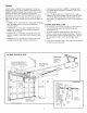
Preparingyour garagedoor Beforeyou begin: • Disable locks. • Removeany ropes connected to garage door. • Complete the followingtest to make sure your garage door is balanced and is not sticking or binding: 1. Lift the door about halfway as shown. Releasethe door. If balanced, it should stay in place, supported entirely by its springs. 2. Raiseand lower the door to see if there is any binding or sticking.
P_nnmg Identify the type and height of your garage door. Survey your garage area to see if any of the conditions below apply to your installation. Additional materials may be required. You may find it helpful to refer back to this page and the accompanying illustrations as you proceed with the installation of your opener. Do you havean access door in addition to the garage door? If not, Model 53702 Emergency Key Releaseis required. See Accessories page. Look at the garage door where it meets the floor.
Planning(Continued) ONE-PIECEDOORINSTALLATIONS Without a properly working safety reversal system, persons (particularly small children) could be SERIOUSLYINJUREDor KILLEDby a closing garage door. • The gap between the bottom of the garage door and the floor MUST NOT exceed 1/4" (6 mm). Otherwise, the safety reversal system may NOT work properly. • The floor or the garage door MUST be repaired to eliminate the gap. • Generally, a one-piece door does not require reinforcement.
CartonInventory Your garage door opener is packaged in one carton which contains the motor unit and all parts illustrated below. Accessories will depend on the model purchased. If anything is missing, carefully check the packing material. Parts may be stuck in the foam. Hardwarefor assembly and installation is shown on the next page.Savethe carton and packing material until installation and adjustment is complete.
HardwareInventory Separateall hardware and group as shown below for the assembly and installation procedures.
ASSEMBLY STEP 1 Assemble the Rail & Install the Trolley To prevent INJURYfrom pinching, keep hands and fingers away from the joints while assembling the rail. To avoid installationdifficulties, do not run the garagedoor opener until instructedto do so. Thefront raft has a cut out "window" at the door end (see illustration). The hole above this windowis larger on the top of the rail than on the bottom. A smaller hole 3-1/2" (8.9 cm) away is close to the rail edge.
ASSEMBLY STEP 2 Fastenthe Rail to the Motor Unit • Insert a 1/4"-20x2-1/2 bolt, washer and spacer into the cover protection bolt hole on the back end of the rail as shown. Tighten securely with a 1/4"-20 lock nut. DO NOToverfighten. To avoid SERIOUSdamageto garage door opener, use ONLY those bolts/fasteners mounted in the top of the opener. • Removethe two bolts from the top of the motor unit.
ASSEMBLY STEP 4 Install the Chain/Cable To avoid possible SERIOUSINJURYto fingers from moving garage door opener: • ALWAYS keephand clear of sprocket while operating opener. • Securely attach chain spreader BEFOREoperating. 1. Pull the cable around the idler pulley and toward the trolley. 2. Connectthe cable to the retaining slot on the trolley, as shown (Figure 1): • From below, push pins of master link bar up through cable link and trolley slot. • Push master link cap over pins and past pin notches.
ASSEMBLY STEP 5 Tightenthe Chain • Spin the innernut and lock washer down the trolley threaded shaft, away from the trolley. Figure1 Outer Lock Nut Washer • To tighten the chain, turn outer nut in the direction shown (Figure 1). Trolley Threaded Shaft To Tighten Outer Nut • When the chain is approximately 1/4" (6 mm) above the base of the rail at its midpoint, re-tighten the inner nut to secure the adjustment. Inner Nut To Tighten Inner Nut Sprocket noise can result if chain is too loose.
INSTALLATION STEP 1 Determine the Header BracketLocation OPTIONAL CEILING MOUNT FOR HEADER BRACKET Unifliinng he_ Header Wall To prevent possible SERIOUSINJURYor DEATH: • Header bracket MUST be RIGIDLYfastened to structural support on header wall or ceiling, otherwise garage door might NOTreverse when required. DO NOTinstall header bracket over drywall. • Concrete anchors MUST be used if mounting header bracket or 2x4 into masonry.
INSTALLATION STEP Install the HeaderBracket 2 You can attach the header bracket either to the wall above the garage door, or to the ceiling. Follow the instructions which will work best for your particular requirements. Do not install the header bracket over drywall.
INSTALLATION STEP 3 Attach the Raft to the Header Bracket • Position the opener on the garage floor below the header bracket. Use packing material as a protective base. NOTE: If the door spring is in the way you'll need help. Have someone hold the opener securely on a temporary support to allow the rail to clear the spring. • Position the rail bracket against the header bracket. • Align the bracket holes and join with a clevis pin 5/16"x1-1/2" as shown. • Insert a ring fastener to secure.
INSTALLATION STEP 4 Positionthe Opener To prevent damage to garage door, rest garage door opener rail on 2x4 placedon top section of door. Follow instructions which apply to your door type as illustrated. SECTIONALDOOROR ONE-PIECEDOORWITH TRACK A 2x4 laid flat is convenient for setting an ideal door-to-rail distance. • Removefoam packaging. • Raisethe opener onto a stepladder. You will need help at this point if the ladder is not tall enough.
INSTALLATION STEP 5 Hangthe Opener To avoid possible SERIOUSINJURYfrom a falling garage door opener, fasten it SECURELYto structural supports of the garage.Concrete anchors MUST be used if installing ANY brackets into masonry. Three representative installations are shown. Yours may be different. Hanging brackets should be angled (Figure 1) to provide rigid support. On finished ceilings (Figure 2 and Figure3), attach a sturdy metal bracket to structural supports before installing the opener.
INSTALLATION STEP Install the DoorControl 6 To prevent possible SERIOUSINJURYor DEATHfrom electrocution: parts of door. Locate door control within sight of door, at a minimum height of 5 feet (1.52 m) where small children cannot reach, away from moving parts of door and door hardware. • Be sure power is NOTconnected BEFOREinstalling door control. 1.
INSTALLATION STEP 7 Install the Lights To prevent possible OVERHEATINGof the endpanel or light socket: • Install a 75 watt maximum light bulb in the socket. Light bulb size should be A19, standard neck only. The lights will turn ON and remain lit for approximately 4-1/2 minutes when power is connected. Then the lights will turn OFF. • DO NOT use short neck or specialty light bulbs. • DO NOT use halogen bulbs. Use ONLYincandescent. To prevent damage to the opener: • DO NOT use bulbs larger than 75W.
INSTALLATION STEP 9 Electrica/ Requirements To prevent possible SERIOUSINJURYor DEATHfrom electrocution or fire: To avoid installation difficulties,do not run the opener at this time. • Be sure power is NOTconnected to the opener, and disconnect power to circuit BEFOREremoving cover to establish permanent wiring connection. • Garagedoor installation and wiring MUSTbe in compliance with ALL local electrical and building codes.
INSTALLATION STEP 10 Install TheProtectorSystem Be sure power is NOTconnected to the garage door opener BEFOREinstalling the safety reversing sensor. To prevent SERIOUSINJURYor DEATHfrom a closing garage door: The safety reversingsensormust be connectedand aligned correctlybeforethe garage door openerwill move in the down direction. IMPORTANTINFORMATIONABOUTTHE SAFETYREVERSING SENSOR When properly connected and aligned, the sensor will detect an obstacle in the path of its electronic beam.
INSTALLINGTHE BRACKETS Figure I Be sure power to the opener is disconnected.Install and align the brackets so the sensors will face eachother across the garage door, with the beam no higher than 6" (15 cm) abovethe floor. They may be installed in one of three ways, as follows. DOORTRACK MOUNT (RIGHT SIDE) t Door , Track Garage door track installation(preferred): • Slip the curved arms over the rounded edge of each door track, with the curved arms facing the door.
MOUNTINGAND WIRINGTHE SAFETYREVERSINGSENSORS Figure 5 • Slide a 1/4"-20xl/2" carriage bolt head into the slot on each sensor. Use wing nuts to fasten sensors to brackets, with lenses pointing toward each other across the door. Be sure the lens is not obstructed by a bracket extension (Figure 5). Wing Nut 1/4"-20 • Finger tighten the wing nuts. • Runthe wires from both sensors to the opener. Use insulated staples to secure wire to wall and ceiling.
INSTALLATION STEP Fasten the DoorBracket 11 Fiberglass, aluminum or lightweight steel garage doors WILL REQUIREreinforcement BEFOREinstallation of door bracket. Contact your door manufacturer for reinforcement kit. Follow instructions which apply to your door type as illustrated below or on the following page. A horizontal reinforcementbrace shouldbe long enoughto be securedto two or three vertical supports.A vertical reinforcementbrace shouldcover the height of the top panel.
ONE-PIECEDOORS Please read and comply with the warnings and reinforcement instructions on the previous page. They apply to one-piece doors also. • Center the door bracket on the top of the door, in line with the header bracket as shown. Mark either the left and right, or the top and bottom holes. HARDWARESHOWN ACTUALSIZE ,, Metal Doors: Drill 3/16" pilot holes and fasten the bracket with the 1/4"-14x5/8" self-threading screws provided.
INSTALLATION STEP 12 Pulley ConnectDoorArm to Trolley _ i÷-8" (20 cm) rain. ...) :: Follow instructions which apply to your door type as illustrated below and on the following page. SECTIONALDOORSONLY II M TrolleyIol "i Iol I / • Make sure garage door is fully closed. Pull the emergency releasehandle to disconnect the outer trolley from the inner trolley. Slide the outer trolley back (away from the pulley) about 8" (20 cm) as shown in Figures 1,2 and 3.
ALLONE-PIECEDOORS Figure5 CORRECT 1. Assemb/ethe door arm, Figure5: INCORRECT IMPORTANT:Thegroove on the straight door arm MUST face away from the curved door arm. • Fastenthe straight and curved door arm sections together to the longest possible length (with a 2 or 3 hole overlap). • With the door closed, connect the straight door arm section to the door bracket with the 5/16"x1-1/4" clevis pin. • Securewith a ring fastener. 2.
ADJUSTMENT STEP 1 Adjustthe UPand DOWN TravelLimits Without a properly installed safety reversal system, persons (particularly small children) could be SERIOUSLYINJUREDor KILLEDby a closing garage door. • Incorrect adjustment of garage door travel limits will interfere with proper operation of safety reversal system. • If one control (force or travel limits) is adjusted, the other control may also need adjustment. • After ANY adjustments are made, the safety reversal system MUST be tested.
ADJUSTMENT STEP 2 Adjustthe Force Without a properly installed safety reversal system, persons (particularly small children) could be SERIOUSLYINJUREDor KILLEDby a closing garage door. • Too much force on garage door will interfere with proper operation of safety reversal system. • NEVERincreaseforce beyond minimum amount required to close garage door. • NEVERuseforce adjustments to compensate for a binding or sticking garage door.
ADJUSTMENT STEP 3 Testthe SafetyReversalSystem Without a properly installed safety reversal system, persons (particularly small children) could be SERIOUSLYINJUREDor KILLEDby a closing garage door. • Safety reversal system MUSTbe tested every month. • If one control (force or travel limits) is adjusted, the other control may also need adjustment. • After ANY adjustments are made, the safety reversal system MUST be tested. Door MUST reverse on contact with 1-1/2" high (3.
OPERATION IMPORTANTSAFETYINSTRUCTIONS To reducethe risk of SEVEREINJURYor DEATH: 1. READAND FOLLOWALL WARNINGSAND INSTRUCTIONS. 2. ALWAYS keep remote controls out of reach of children. NEVER permit children to operate or play with garage door control push buttons or remote controls. 3. ONLYactivate garage door when it can be seen clearly, it is properly adjusted, and there are no obstructions to door travel. 4. ALWAYS keepgarage door in sight until completely closed.
Usingthe Wall-MountedDoor Control To Openthe DoorManually THE DOORCONTROLBUTTON Press the lighted push button to open or close the door. Press again to reverse the door during the closing cycle or to stop the door while it's opening. To prevent possible SERIOUSINJURYor DEATHfrom a falling garage door: • If possible, use emergency releasehandle to disengage trolley ONLYwhen garage door is CLOSED.Weak or broken springs or unbalanceddoor could result in an open door falling rapidly and/or unexpectedly.
CARE OF YOUR OPENER THE REMOTECONTROLBATTERY LIMIT AND FORCEADJUSTMENTS: Weather conditions may cause some minor changes in door operation requiring some re-adjustments, particularly during the first year of operation. Pages27 and 28 refer to the limit and force adjustments. Only a screwdriver is required. Follow the instructions carefully. FORCECONTROLS To prevent possible SERIOUSINJURYor DEATH: • NEVERallow small children near batteries. • If battery is swallowed, immediately notify doctor.
HAVING A PROBLEM? 1. My doorwill not close and the light bulbs blink on my motor unit: The safety reversing sensor must be connected and aligned correctly before the garage door opener will move in the down direction. Bell Wire • Verify the safety reversing sensors are properly installed, aligned and free of any obstructions. Refer to Installation Step 10: Instafl TheProtector System. • Checkdiagnostic LEDfor flashes on the motor unit then refer to the Diagnostic Chart on the following page. 2.
Bell Wire I 1 Safety Reversing Sensors Your garage door opener is programmed with self-diagnostic capabilities. The "Learn" button/diagnostic LED will flash a number of times then pause signifying it has found a potential issue. Consult Diagnostic Chart below. Diagnostic Chart • Safety reversingsensorswire open(broken or disconnected). Symptom:One or both of the Indicator fights on the safety reversingsensorsdo not glow steady.
PROGRAMMING NOTICE:If this Security,I_ garage door opener is operated with a non-rolling code transmitter, the technical measure in the receiver of the garage door opener, which provides security against code-theft devices, will be circumvented. Theowner of the copyright in the garage door opener does not authorize the purchaser or supplier of the non-rolling code transmitter to circumvent that technical measure.
To Add, Reprogram or Change a Keyless Entry PIN NOTE: Your new KeylessEntry must be programmed to operateyour garage door opener. USINGTHE "LEARN" BUTTON Tochangean existing, knownPIN If the existing PIN is known, it may be changed by one person without using a ladder. 1. Press the four buttons for the present PIN, then press and hold the # button. The opener light will blink twice. Releasethe # button. 2. Press the new 4-digit PIN you have chosen, then press ENTER.
REPAIR PARTS 3 41A5665 Complete rail 4 144C56 Idler pulley 5 41A5595 Chain and cable 6 12D598-1 "U" bracket NOT SHOWN 183A163 Wear pads InstallationParts D KEY PART NO. NO.
Motor Unit Assembly Parts 4 I I 5 7 19 18 17 16 Brown Wire \ (Down) Contact \/"'_ 15 LIMIT SWITCH ASSEMBLY 14 12 Gr_ _4"--.",L _ Drive _ - ................ / t Gear _J_ffllf_/fffff_ CenterL:imit (Up) contact contact KEY PART NO. NO. _t' Wire d, L,',,',,',,',,',,',_J Yellow wire DESCRIPTION KEY PART NO. NO.
ACCESSORIES 7 EmergencyKeyrelease: Required for a garage with NOaccess door. Enableshomeowner to open garage door manually from outside by disengaging trolley. 139.53728 8 Foot (2.4 m) Rail Extension: OR 139.53729 10 Foot (3 m) Rail Extension: To allow an 8 foot (2.4 m) or a 10 foot (3 m) door to open fully. 41A5281 ExtensionBrackets: (Available onlythroughSears Parts & Service) 139.53687 Premium ControlConsole: Provides a lock feature to prevent operation of garage door from portable remotes.
CONTENIDO Introducci6n 2-7 Ajustes 27-29 Revisi6n de los simbolos y t_rminos de seguridad ................. 2 Ajuste el limite del recorrido .................................. 27 Preparaci6n de la puerta de su cochera .......................... Herramientas necesarias...................................... 3 3 Ajuste lafuerza ............................................ 28 Pruebe el sistema de retroceso de seguridad ..................... Pruebe el Sistema de Protecci6n® ..........................
Preparaci6nde la puerta de su cochera Antes de comenzar: Para evitar una LESIONGRAVEo INCLUSOLA MUERTE: • Quite los seguros. • Retire cualquier cuerda o cable que est_ conectado a la puerta. • Haga la siguiente prueba con su puerta para verificar que est_ balanceaday que no se atore ni se pandee: • SIEMPRE Ilamea un t_cnico profesional para que le d_ servicio a su puerta de cochera si _sta se atora, se pandeao est,. desbalanceada.
Planificaci6n Identifique laaltura y el tipo de su puerta de cochera. Reviseel _.reade su cochera y observe si alguna de las siguientes instalaciones corresponden a la suya. A veces se requieren materiales adicionales, asi quetal vez sea conveniente tener esta hoja y las ilustraciones correspondientes a mano cuando inicie la instalaci6n de su abridor. _,Hayotra puerta que d_ acceso a la cochera? Si no es asi, ser_. necesario contar con el sistema de Ilave de emergencia Modelo 53702. Vea la p_.
Planificaci6n(contin#a) INSTALACIONCON PUERTASDE UNASOLAPIEZA Sin un sistema de retroceso de seguridad que funcione debidamente, al cerrar la puerta de la cochera se corre el riesgo de que las personas (yen particular los ni_os peque_os) sufran LESIONESGRAVESo INCLUSOLA MUERTE. • Generalmenteuna puerta de una sola pieza no requiere refuerzos adicionales.
Inventario de la Cajade Cart6n Su abridor viene empacado en una caja de cart6n que contiene el motor y las piezas que se muestran en la siguiente ilustraci6n. Tome nota de que los accesorios depender_.ndel modelo que haya comprado. Si falta alguna pieza, revise con cuidado el material de empaque ya que en ocasiones las piezas se atoran en el mismo. Toda la tornilleria y las piezas necesarias para el montaje e instalaci6n de su puerta se ilustran en la siguiente p_.gina.
Inventario de Piezas Antes de la instalaci6n, organice todas las piezas en grupos como se muestra en la siguiente ilustraci6n. TORNILLERIA Y PIEZASPARAELMONTAJE Tuercade 1/4-20 (2) Arandela 5/8 pulg. (2) Arandela de 3/8 pulg. (1) Tuercade 3/8 pulg.(1) i i Perno de 1/4-20xl-3/4 pulg. (1) Enlaeemaestro(2) Separador(2) Perno de 1/4-20x2-1/2de pulg.(1) PernoIoco (1) [© Flecha roscada del trole (1) TORNILLERIA Y PIEZASPARALAINSTALACION O Perno deeoche de 1/4-20xl/2 pulg.
MONTAJE, PASO 1 Monte e/fie/e insta/e e/tro/e No encienda ni use el abridorhasta que Ilegue al paso de la instalaci6n correspondiente,de otra manera corre el riesgo de complicar el proceso de instalaci6n. El riel delaiTterotieiTeuiTa"veiTtaiTa"cortada ei7el extremo de la puerta (vea la ilustracibn). El orificioque se encuentrapor encima de esta ventana es mbs grande en /a parte superior de/fie/que en /aparte inferior. Hay un orificio m_s pequeffo que se encuentra a 8.9 cm (3-1/2 de pulg.
MONTAJE, PASO 2 Fije el riel a la unidadde/motor • Introduzca un tornillo de 1/4-20 x 2-1/2 de pulg., con arandela y separador, en el agujero del perno de protecci6n de latapa ubicado en la parte trasera del riel (tal como se muestra).Ajuste firmemente con una tuerca de seguridad de 1/4 de pulg.-20. NO ajuste demasiado la tuerca. Use SOLOel perno y la tuerca que vienen montados en la parte superior del abridor para evitar que el abridor de la puerta de cochera se da_e SERIAMENTE.
MONTAJE, PASO 4 Instale la cadenay cab/e Para evitar posibles LESIONESGRAVESen los dedos causadaspor las partes m6viles del abridor de puerta de cochera: • SIEMPREmantenga las manos lejos de la rueda dentada mientras est_ funcionando el abridor. 1. Jale el cable alrededor de la polea Ioca y hacia el trole. 2. Conecte la cable a la ranura de retenci6n del trole, como se muestra en la ilustraci6n (Figura 1): • Empuje los pernos de la barra de enlace maestro desde abajo hacia arriba y p_.
MONTAJE, PASO Apriete la Cadena 5 • Gire la tuerca interna y ajuste la arandela; baje ambas por el eje roscado del trole, alej_.ndolasdel trole. Figura1 • Para apretar la cadena, gire la tuerca externa en la direcci6n que se indica (Figura 1). Paraapretar Tuerca externa Arandela Eje roscado del trole • Una vez que la cadena est_ aproximadamente a 6 mm (1/4 de pulg.) por encima de la base del riel en su punto medio, vuelva a apretar la tuerca interna para asegurar el ajuste.
INSTALACION, PASO 1 Cielo raso sin acabado -- Determine d6nde vaa insta/ar /a m_nsu/ade/cabeza/ Pared delantera Para evitar una posible LESIONGRAVEo INOLUSOLA MUERTE: • La m_nsula del cabezalDEBEquedar RJGIDAMENTEsujeta al soporte estructural en la pared delantera o en el cielo raso, de no ser asi es posible que la puerta de la cochera no retroceda cuando se requiera. NO instale la m_nsula del cabezal en muros falsos.
INSTALACION, PASO 2 Instale la M_nsula de/Cabezal Montaje en la pared La m_nsula del cabezal se puedefijar a la pared justo por encima de la puerta de la cochera o en el cielo raso. Siga las instrucciones que sean m_.sadecuadas para su cochera. No instale la m_nsula del cabezal en un muro falso. Si va a fijar la m_nsula del cabezal a ladrillo o mamposteria, aseghrese de utilizar sujetadoresde cemento (no se inclupen).
INSTALAClON, PASO 3 Coloque el Riel en la M_nsula de/Cabezal • Coloque el abridor sobre el piso de la cochera debajo de la m_nsula del cabezal. Use el material de empaque como base para protegerlo. NOTA:Si el resorte de la puerta est# obstruyendo, va a necesitar ayuda. Otra persona tendr# que sostener el abridor firmemente sobre un soporte temporal para permitir que el rid pueda librar el resorte. • Coloque la m_nsula del riel contra la m_nsula del cabezal.
INSTALACION, PASO 4 Coloque el Abridor en Posici6n Para evitar que la puerta de cochera sufra da_os, apoye el riel del abridor de la misma sobre un pedazode madera de 5x10 cm (2x4 pulg.) colocado en la secci6n superior de la puerta. Siga las instrucciones correspondientes al tipo de puerta de su cochera, como se muestra en la ilustraci6n. PUERTASECCIONAL0 PUERTADE UNASOLAPIEZACON CARRIL Un pedazode madera de 5x10 cm (2x4 pulg.) le ser_.de ayuda al determinar la distancia ideal entre la puerta y el riel.
INSTALACION, PASO 5 Cuelgueel abridor Para evitar la posibilidad de una LESIONGRAVEsi se cae el abridor de la puerta de cochera, suj_telo FIRMEMENTEa los soportes estructurales de la cochera. Se DEBENusar sujetadores para concreto si alguna de las m_nsulas se va a instalar en mamposteria. Aqui se muestran tres ejemplos distintos para la instalacidn; sin embargo, es posible que su cochera no concuerde con ninguno de ellos. Las m_nsulas de soporte deben estar en _.
INSTALACION, PASO 6 Instale la unidadde controlde la puerta Para evitar la posibilidad de una LESIONGRAVEo INCLUSOLA MUERTEpor electrocuci6n: • ANTES de instalar el control de la puerta, cerci6rese de que la energia el_ctrica no est_ conectada. Ubique el control de la puerta de manera que quede a lavista desde la puerta y a una altura minima de 1.5 m (5 pies) donde los ni_os peque_os no Io puedan alcanzary lejos de las partes m6viles de la puerta y de la tornilleria.
INSTALACION, Instale /as luces • PASO 7 Para evitar un posible SOBRECALENTAMIENTO del portabombillas: • NO utilice bombillas de cuello corto ni de tipo especial. • NO utilice bombillas hal6genas. Utilice SOLObombillas incandescentes. Para evitar dafio al abridor: Instale bombillos de 75 vatios como m_.ximoen cada portal_.mpara. Los bombillos deben ser de A19 cuello standard s61o.En cuanto se conecte la electricidad, las luces se encender_.ny permanecer_.
INSTALACION, PASO 9 Requisitos parala instalaci6nel ctrica Para evitar la posibilidad de una LESIONGRAVEo INCLUSOLA MUERTEpor electrocuci6n o incendio: • Cerci6rese de que el abridor no est_ conectado a la energia el_ctrica, y desconecte la alimentaci6n el_ctrica al circuito ANTESde quitar la cubierta para establecer la conexi6n del cableado permanente. • Tanto la instalaci6n como el cableado de la puerta de cochera DEBEN cumplir con todos los c6digos locales de construcci6n y el6ctricos.
INSTALACION, PASO 10 Instale e/Sistema de Protecci6n Cerci6rese de que la energia el_ctrica no est_ conectada al abridor de la puerta de la cocheraANTES de instalar el sensor del sistema de retroceso de seguridad. Para evitar una LESIONGRAVEo INCLUSOLA MUERTEcuando la puerta de la cochera se est,. cerrando: • Conectey alinee correctamente el sensor del sistema de retroceso de seguridad. Este dispositivo de seguridad es necesario y NO SE DEBE desactivar.
INSTALACIONDE LAS MENSULAS Figura1 Aseg_resede que el abridor no est_ conectadoa la corrienteel_ctrica. INSTALACIONEN EL CARRILDE LA PUERTA(LADO DERECHO) I I_l_Oarri, de Instale y alinee las m_nsulas de manera que los sensores est_n uno frente al otro en los lados opuestos de la puerta, a una distancia m_.ximade 15 cm (6 pulg.) del piso.
MONTAJEY CABLEADODE LOS SENSORESDEL SISTEMA DE SEGURIDADDE REVERSA Figura5 Tuerca de mariposa 1/4-20 de pulg. • Deslice la cabezade un perno de coche de 1/4-20xl/2 de pulgada dentro de la ranura de los sensores. Usetuercas de mariposa para sujetar los sensores alas m_nsulas, con las lentes de cadasensor frente a frente a ambos lados de la puerta. Cerci6resede que la extensi6n de la m_nsula no obstruya las lentes (Figura 5). Pernodecoohe de _ 1/4-20xl/2 depulg. • Apriete las tuercas de mariposa a mano.
INSTALACION PASO 11 Fije la mGnsula de la puerta En puertas de garaje de fibra de vidrio, aluminio o acero liviano ES NEOESARIOcolocar los refuerzos ANTESde instalar la m_nsula de la puerta. Consulte con el fabricante de la puerta sobre juegos prefabricados de refuerzo. Siga las instrucciones que correspondan al tipo de puerta que usted tenga, seg_n las ilustraciones siguientes o de la pr6xima p_.gina.
PUERTAS DE UNA SOLA PIEZA: Lea y respetetodas las advertencias e instrucciones respecto a los refuerzos contenidas en la p_.ginaanterior, ya que son v_Jidastambi_n para puertas de una sola pieza. • Centre la m_nsula en la parte superior de la puerta, alineadacon la m_nsula del cabezal, tal se muestra en la ilustraci6n. Marque ya sea los orificios derecho e izquierdo o superior e inferior. ESTASPIEZASSE MUESTRANEN SU TAMANO REAL • Puertas met#licas: Haga agujeros guia de 3/16 de pulg.
INSTALACION, PASO 12 Conecteel brazodela puertaal trole Polea : Lo menos 20 cm : A'- _8,.ig.) __: Siga las instrucciones que correspondan al tipo de puerta de cochera que usted tenga, como se muestra a continuacien yen la pD.ginasiguiente. SOLOPARA PUERTASSECCIONALES Figura 1 tope del • Cercierese de que la puerta de la cochera est_ completamente cerrada. Tire de la manija de emergencia para desconectar el trole exterior del trole interior. Desliceel trole exterior hacia atrD.
TODAS LASPUERTASDE UNASOLAPIEZA Figura 5 CTO 1. Arme el brazode/a puerta, Figura 5: RECTO IMPORTANTE:El ranura el7el brazo recto de la puerta DEBEvolt#ese del brazo curvado de la puerta. • Sujete las dos secciones de los brazos de la puerta (recto y curvo) a la mayor distancia posible, de manera que dos o tres de los orificios se sobrepongan uno al otro. • Cierre la puerta y fije la secci6n recta del brazo a la m_nsula de la puerta con el pasador de chaveta de 5/16x1-1/4 de pulgada.
AJUSTES, PASO 1 Ajuste e//imite HACIA ABAJO de/recorrido HACIA ARRIBA y Si el sistema de retroceso de seguridad no se ha instalado debidamente, las personas (y los niSos pequeSosen particular) podrian sufrir LESIONESGRAVESo INCLUSOLA MUERTEcuando se cierra la puerta de la cochera. • El ajuste incorrecto de los limites del recorrido de la puerta de la cochera interferir_,con la operaci6n adecuada del sistema de retroceso de seguridad.
AJUSTES, PASO Ajuste la Fuerza 2 Si el sistema de retroceso de seguridad no se ha instalado debidamente, las personas (y los ni_os peque_os en particular) podrian sufrir LESIONESGRAVESo INCLUSOLA MUERTEcuando se cierra la puerta de la cochera. • Si el limite de la fuerza de la puerta de la cochera es excesivo interferir_, con la operaci6n adecuada del sistema de retroceso de seguridad. Los controles para el ajuste de la fuerza del abridor se encuentran en el panel de posterior de la unidad del motor.
AJUSTES, PASO 3 Pruebee/sistemaderetrocesodeseguridad Si el sistema de retroceso de seguridad no se ha instalado debidamente, las personas (y los ni_os peque_os en particular) podrian sufrir LESIONESGRAVESo INCLUSOLA MUERTEcuando se cierra la puerta de la cochera. • El sistema de retroceso de seguridad SE DEBEprobar cada mes. • Si se ajusta uno de los controles (limites de lafuerza o del recorrido), es posible que sea necesarioajustar tambi_n el otro control.
OPERACION INSTRUCCIONESIMPORTANTESDE SEGURIDAD Para reducirel riesgode LESIONESGRAVESo LAMUERTE: 1. LEA Y SIGA TODASLAS ADVERTENCIASY LAS INSTRUCCIONES DE OPERACION. 9. Cuando se ajusta uno de los controles (limites de fuerza o de recorrido), es posible que sea necesarioajustar tambi_n el otro control. 2. SIEMPRE conserve los controles remotos fuera del alcance de los ni_os. NUNCApermita que los ni_os operen o jueguen con los botones del control de la puerta de la cochera ni con los controles remotos.
C6mousar/a unidadde contro/de pared C6mo abrir /a puerta manua/mente BOTONDE CONTROLDE LA PUERTA Oprima el bot6n iluminado para abrir o cerrar la puerta. Optima de nuevo para que la puerta retroceda en el ciclo de cierre o para detener la puerta cuando se est,. abriendo. Para evitar la posibilidad de una LESIONGRAVEo INCLLISOLA MUERTEsi la puerta de la cochera se cae: • Deser posible, use la.manila de liberaci6n de emergencia para soltar eltrole SOLOcuando la puerta de la cochera est_ CERRADA.
MANTENIMIENTO DE SU ABRIDOR PUERTA DE COCHERA LA BATERIADEL CONTROLREMOTO DE AJUSTESDE LIMITE Y FUERZA: Las condiciones climatol6gicas pueden ocasionar cambios menores en la operaci6n de la puerta, los cuales van a requerir algunos reajustes, en particular durante el primer afio de operaci6n. En las p_.ginas27 y 28 se encuentra la informaci6n sobre los ajustes de limite y de fuerza. Lo _nico que necesita es un destornillador. Siga las instrucciones con cuidado.
Si tiene alg_n prob/ema 1. La puerta no cierra y las luces de la unidad del motorparpadean: El sensor del sistema de retroceso de seguridad debe estar instalado y alineadocorrectamente para que el sistema de apertura de la puerta de la cochera se mueva en sentido descendente. Cable de campana • Aseg_rese de que los sensores de seguridad est_n instalados y alineados correctamente, y que est_n libres de obstrucciones. Consulte la secci6n Instalaci6n, Paso 10: Instale EISistema de Protecci6n.
Cable de campana El sbtema de apertura de la puerta cuenta con una funciSn de autodiagn6stico. El bot6n "Aprender"/LED de diagn6stico parpadear_ varias veces antes de detenerse, indicando que ha encontrado un posible problem& Consulte la tabla de diagn6stico a continuaci6n. Sensor de seguridad de reversa Tab/a de Oiagn6stico • El circuito de los sensoresde seguridadde reversaest_ abierto (cable rotoo desconectado).
COMO PROGRAMAR EL ABRIDOR A VISO:Si utiliza este abre puertas de garaje Security,F _ con un transmisor no dotado de un sistema de c6digos de salto (c6digo aleatorio), se ver_n circunvenidas las medidas t_cnicas incorporadas en el receptor del abridor para proteger contra los aparatos de captura de c6digos.
C6moagregar, reprogramaro cambiar un c6digode entradasin l/ave NOTA:Su nueva Entrada sin Ilave debe programarse para que opere el abridor de la puerta de su cochera. COMOUSAR EL BOTONLEARN(APRENDER) Para cambiar un PIN existente Si el PIN existente ya es conocido, una persona Io puedecambiar sin usar una escalera. 1. Oprima los cuatro botones que correspondan al PIN actual, luego oprima y mantenga oprimido el bot6n #. La luz del abridor parpadear_,dos veces. Suelte el bot6n #. 2.
ACCESORIOS 139.53687 Liberador de la Ilave de emergencia: Provides a lock feature to prevent operation of garage door from portable remotes. A light feature controls the opener lights. Can be usedto program the opener to accept additional remotes. Se requiere en las cocheras que NO tienen puerta de acceso. Permite al dueSo de la casa abrir la puerta de la cochera manualmente desde el exterior, desconectando el trole. 139.53728 139.53729 Extensi6n del rielde2.
Your Home For troubleshooting, product manuals and expert advice: www.managemylife.com For repair - in your home - of all major brand appliances, lawn and garden equipment, or heating and cooling systems, no matter who made it, no matter who sold it! For the replacement parts, accessories and owner's manuals that you need to do-it-yourself. For Sears professional installation of home appliances and items like garage door openers and water heaters.